Insane Hydraulics
Bold and audacious blog about fluid power
Self-excited oscillations of hydraulic pump and motor controls are the topic I could discuss for hours. This interesting and extensive subject can involve tons of theory and math if one's up to it, but since this blog is more practical than scientific, I want to devote this post to a simple trick that can be used not only to fix a "swingy" pump control but also be applied to other "self-oscillating hydraulic situations".
The trick can be described as "adding leakage" to the control fluid, and by control fluid I mean - hydraulic fluid, which is directed from a control spool to a servo-cylinder, and by leakage, I mean restricted (with a calibrated orifice) connection to the tank.
You will find it in many pump control valves - that tiny orifice that creates a leak in the servo-pressure line. It is there for a reason, in case you wondered, for several reasons actually. For one - the leakage flow helps to cool the pump, especially in standby or dead-head modes. But its main purpose is to resolve control instability issues.
How does it do that? Very simple, if you think about it. A pump control valve is nothing but a pressure control that is supposed to dynamically change the pressure in the servo-cylinder. When a servo cylinder is "leak-free", the control system is very "stiff", if you will, and even the tiniest change in the position of the control spool can result in large pressure swings inside the servo-cylinder. Such systems are fast but are prone to self-oscillations. When you introduce a small leakage to the servo pressure, you are effectively "damping" the control system, because you are "forcing" the control spool to be constantly supplying a small amount of oil, and thus shift its working position to a more stable zone.
The following thought experiment may help with visualizing the concept:
Imagine that you have a pressure gauge connected to your kitchen faucet (blocking its outlet), your household water pressure is 50 PSI, and your job is to make sure the pressure gauge is reading, say, 15 PSI. As you can imagine - you will have to "crack" the faucet ever so slightly, wait until the gauge reaches 15 PSI, and then immediately close it. If you overdo it, you'll have to find a way to vent the excessive pressure, so maybe you'll "tee in" a second tap to create your "tank" connection. The two taps now form a three-way two-position valve (as long as you operate one tap at a time), and you will most likely have to take several "tap takes" to reach the desired pressure.
Now imagine that you drilled a small hole in the outlet of your "pressure control system". There's a small leakage now, and you will see that all you need to do is crack just one faucet (pressure-side) in order to maintain the target pressure stable, and it's much easier to control now. Crack the faucet a bit more - the pressure goes up, close it a little - the pressure goes down. See how you just traded a small amount of leakage for better and more stable control?
From theory to practice! Let me show you a real-life example of how controlling the amount of servo-fluid leakage solved the problem of unwanted self-oscillation in the high-pressure cut-off control of a Rexroth A7VO open circuit pump. I also have a video that contains the pressure readings at different stages of the "experiment", but you should read the description before watching it, otherwise, it won't make much sense.
The problem - a Rexroth A7VO55LR3E/61L open circuit pump, equipped with torque limiter and high pressure cut off control, both with hydraulic overrides (more detail on this particular model here), was exhibiting violent self-oscillating behavior in the dead-head condition, when the cut-off was kicking in. This is the hydraulic diagram (the "X" above "T1" is an orifice, not a plug):

And this is the cutaway schematic of the control:

One might expect that such self-sustained oscillations could be fixed by strangulating the control flow with a "strategically placed" orifice - but I found that most of the time it results in nothing but an increased response time, which is highly undesirable. This pump actually had a thread in the control gallery (cut-view), so this was easy to test. Placing a 0.8mm orifice in this channel not only didn't solve the self-oscillation issue but also resulted in an unacceptably slow response time of the cut-off, which can be seen by the 350 bar pressure spike, easily visible even on the analog pressure gauge in the second part of the video.
If you look at the diagram, you'll see that there is a small orifice in the T1 port, that provides the control fluid leakage to an external tank line. Since these pumps have no drain (the case is internally connected to the suction line) - the first thing that may come to mind is - it is there to allow the pump to dead-head for longer periods without overheating, as the T1 flow carries away some of the heat generated by the pump. One might assume that, aside from the overheating rate, this control should behave in the same manner with the T1 plugged. Well, if you try it (and I did try it) - you will see that the cut-off does cut-off, but it self-oscillates even more violently than before! This can be seen in the third part of the video.
What we got so far is - no control fluid leakage - violent self-oscillation, some control fluid leakage - less self-oscillation. Let us play around with this tendency a little, shall we? Let us take out the 0.8mm orifice the T1 port was carrying, and connect it to the tank line via a needle valve to be able to infinitely control the leakage. The result can be seen in the fourth part of the video - two things happen as the rate of the leakage increases - the deadhead pressure rises (slightly), and the behavior of the control becomes more and more stable, with the self-oscillations eventually disappearing.
So, we are finally getting somewhere - increasing the amount of the control leakage results in a more stable dead-head condition of our pump. By the way, a "field" variant of the added leakage experiment can be easily performed by means of a small diameter test hose, connected to the X3 port (which already has a conveniently placed test fitting there), with the other end "unloading" into an adequate vessel (very unsafe!). The behavior of the control with this "improvised" added leakage is seen in the next scene - again - no self-oscillations here.
In case you wonder how much leakage the disconnected test hose added - observe the next part, where you can see a one-liter volume, filled by the test hose with the pump dead-headed at 230 bar. The leakage flow is around 4-5 liters per minute.
Several orifice sizes were tested in the T1 port, and in the end, the original 0.8 mm orifice was replaced with a 0.9 mm orifice, which didn't remove the oscillations completely but reduced them to an acceptably low level, with a relatively small increase of the leakage flow. The final result can be seen in the last part of the clip.
Conclusions:
1) Controlled leakage can solve stability issues and reduce self-oscillations. Use this knowledge wisely!
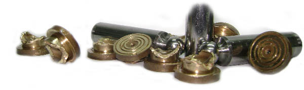
2) A 0.9 mm orifice is different from a 0.8 mm orifice, even though the difference is barely seen with the naked eye:

3) In filed conditions, gauge connecting hoses can serve as a makeshift replacement of an orifice.
And now, for the video: