Insane Hydraulics
Bold and audacious blog about fluid power


Generally, overhauling a hydraulic pump is a four step process - you disassemble it, identify damaged components, replace or re-work them and then re-assemble the pump. Practical, functional and dull.
There's nothing wrong with this. A damaged part is a damaged part, and when you see one - you replace it, that's perfectly fine, except for the fact that if you limit yourself to just that, and don't pay attention to small details about how the part was damaged and what type of wear it has - you're missing out on a lot of useful and sometimes invaluable information that can teach you something new and make you a better tech.
Let me explain what I mean by using this A4VG Rexroth closed loop pump as an example.
I got it last week, and it almost seemed like it had been sent to me on purpose by someone who had read my article about "small big symptoms" I posted a couple of weeks earlier, because it arrived with the usual "the transmission is running perfectly fine, and the only problem is the leaking shaft seal, but since we're overhauling the slew bearings, we might as well take care of the leak".
I double-checked this with the owner, and he confirmed that as far as the speed and force went - the performance of the closed loop transmission was flawless. So, I took a lever from the tool stand and tried to wiggle the shaft - and, sure thing, it moved! The client was very surprised to see the shaft end shift about so much. I guess it's not just the shaft seal now, is it?
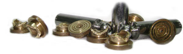
Let us crack the pump open and peek inside, shall we? And as I pull the barrel and the pistons out... Wow!!! What is this? Marvelous! Stunning! Did someone forget a wedding ring inside? Of course not, but still - this is another example of how hydraulic pumps can create beautiful things like flowers and tiny castles!
The cyclic abrasive action of the hard particles between the retainer plate and the piston slippers reduced their height significantly, and caused the outer burr to roll into a perfect ring which separated from one of the slippers and fell down as I pulled the rotary group apart. Note how perfectly round its shape is! And how about this wedding ring with a jewel? Isn't it a beautiful sight to behold? Definitely something you don't find in broken pumps every day!
Naturally - the shaft bearing is busted, but we already knew that. This wide gap between the rollers looks like a smiling pirate with a missing front tooth, don't you think? "Arr, matey! We be putting this bearing into the Davy Jones locker!"
Another detail here - look at the shaft spline behind the bearing - you can clearly see that it's damaged, but it wasn't damaged this time (no respective damage to the swash-plate or anything else) - so this tells me that this pump had definitely suffered a major failure at least once before. It also tells me that the shop that repaired the pump last time did a poor job here - they should have at least deburred the damaged spline.
And how about this swash-plate bearing? The plastic retainer is already cracked. I estimate it would run for another day or two at most before breaking in two and causing a spectacular catastrophic failure. You can see that the swash plate and the bearing liners have deep roller marks, which means that they have a lot of hours on top of them, at least 8,000 to 10,000, maybe more. Still it's interesting to see how close the swash-plate mechanism came to breaking, without actually breaking. Another thing that points to a lot of work hours is the wear of the swash plate bearing pins. I takes a lot of rubbing to create that deep a wear!
Let us inspect the rotary group now. We see lot's of hard particle wear, which is normal for an axial piston unit that suffered a bearing failure. There's heavy wear of the piston slippers and the retainer plate, score marks all over the ball guide, and also the typical cylinder sleeve wear, which shows us that the reciprocating piston movement can draw hard particles from the case fluid into the piston gap and cause scratches on the cylinder block sleeves.
This is a very important lesson here, by the way. All this heavy wear combined with the swash-plate bearing that was almost at the breaking point had absolutely no detectable effect on the performance of the pump.
Talking about it is one thing, seeing is completely different. Seeing is believing! I suggest you bookmark this page to be able to show it to hydraulic equipment owners as an illustration of how a perfectly performing pump can be on the verge of catastrophic failure.
Anything else interesting? How about this eccentric valve plate pin - it's important to know that this pin allows you to alter the timing angle of the valve plate - compare this angle with the more advanced one. Nice design, mr. Rexroth!
Now the charge pump can tell a very interesting story of its own, that is - if you let it, because if you look at it and see but a worn out charge pump - you will be missing out on so much interesting information!
The uni-lateral wear of the central gear key hole will confirm you the direction in which it was rotating, and also the position in which the gear was mounted. This one was mounted in the correct position. The outer gear, however, wasn't. The wear clearly shows that it was mounted incorrectly (the correct chamfer position can be seen here).
What can we learn here? First - the fact that the outer gear ended up in the incorrect position, plus the wear marks present on both sides of the teeth tell me that this part had worked in the correct position first, and then was re-mounted incorrectly. Second - this is a definite proof that the correct mounting position exists for a reason. When the gear is inserted "the other way around" it gets jammed between the pump housing and the metal plate. Look at the opposite side of the plate - you can see that in the spot where the most friction was happening the plate heated up so badly that the the o'ring seal behind it literally charred. Well, at least we know now what happens when this gear is mounted in incorrect position.
Another lesson here - even though the incorrect position of the external gear did cause damage to the charge pump - the unit ran problem free for at least 5000 hours (I know for a fact that the pump clocked about 5000 hours after the machine had been imported). What's the secret here? - It's the presence of the charge pressure filter between the charge pump and the loop!
Two more lessons for you: a closed loop transmission change pump can deliver adequate charge flow even when it's worn out, and lesson two - charge pressure filtration definitely saves the main pump when a charge pressure pump creates contamination due to wear. I never skip charge pressure filtration when I design a closed loop system! Never!
As you see, paying just a tiny bit more attention to small details during an overhaul can teach you a lot. Not always, of course, but often - and the knowledge is invaluable, because you will not find it anywhere (except for this blog, of course).
Let us finish with recapitulating just a few of the "lessons" this particular overhaul could offer free of charge to an attentive overhauler (you decide which ones are useful and which are not):
Hydraulic pumps can generate bronze rings that resemble expensive jewelry.
Certain types of wear can tell you if the pump had been overhauled before.
Wear in the shaft bearing will cause case oil contamination and consecutive excessive wear in the pump components without any symptom of degraded performance.
Severe wear in the swash-plate roller bearings is also not reflected by degraded performance.
Hard particles in the case oil can be drawn into the piston gap and score the sleeve surface.
Some valve plate pins can be eccentric and mounted in two positions altering the timing angle of the valve plate.
If you mount the external gear of a A4VG charge pump "the other way around" it will damage itself, the plate and the housing, but, surprisingly, the pump will work for a long time if the pump is equipped with a charge pressure filter.
A charge pump can have significant amount of wear without causing degraded performance of a closed loop transmission.
Charge pressure filtration is definitely the best way to protect your closed loop pump.
Do bookmark this page for your future reference. Remember - this pump had no performance issues whatsoever!
One more thing - paying attention to small details not only makes the overhauling process a little bit more educational, but also, a little bit more fun.