A
classic here - Sauer Danfoss series 90 closed loop pump, very commonly used in
mobile hydrostatic transmissions. This particular unit is a 100cc pump
from a John Deere forester, I get those all the time, not because
they break a lot, but because they are so widely used.
Here
you can see how the pump looks (AFTER it has been cleaned up, cause
when they brought it to the shop it was completely covered with dirt).
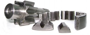
First of all let's discard the obvious dull stuff everybody knows about (pic2),
here we have the shaft, the cylinder block, the pistons, swash plate,
charge pump, servopiston and the servocylinders, and the rest of the
crap (pic3) like bolts, nuts and what not every piston pump has.
On the pic4 you
can see already lapped piston shoes, along with one of
several small differences that always exist between the original
and not original (made in China) parts. On the original block the brass
sleeve is slightly immersed in the body, creating a 1 mm ramped entrance, while
after-market blocks usually don't have it, which makes the "screw-in" mounting technique much harder, as there is no good guidance for the pistons to enter the cylinder block.
Early series 90 came with an all-flat sealing
surface of the cylinder block, while later models have the outer brass ring a
little lower then the kidneys ring, which I am guessing makes it
a better dynamic bearing. Anyway, my own
experiments, which I am going to describe in a separate article,
proved, actually, that lowering outer ring can difficult the block
lift, so after lapping the sealing surface I sometimes lathe the outer
ring down 0.05mm or so (pic5, pic6).
By the way, some models carry the cylinder block that
doesn't have any outer ring at all! I guess the engineers came to a
conclusion that it was not really necessary, at least for that particular application.
Now let's have a closer look at the end-cover (pic7).
Here we can see a pretty standard for modern hydrostatic pumps housing
of a gerotor-type charge pump, with easily identifiable suction and
pressure sides. Note that in this model charge pressure relief valve
connects directly to the pressure side, BEFORE the filter (filtering
option can be disabled or altered for the use of an external filter, by
the way) which means that if you measure the charge pressure from the
port before the filter, you may get false reading. I have seen machines
with a test coupling mounted at this spot. When the filter gets
clogged, the transmission starts loosing charge pressure and
cavitate and yet you still read the normal charge pressure in the
"before" port. I have seen them filters clog pretty bad on these John
Deere (Timberjack in the good old days...) foresters.
The two measuring ports (pic8) might give you a crazy idea of continuous filter state monitoring, by measuring the delta P.
On pic9 and pic10
you can see the inside of the back cover and its connections. Sauer
produces many variations of these. Some, for example, don't have all of
those internal passages, and are meant to be used in applications which
don't require the pressure limiter function. The official Sauer Danfoss website
provides complete pdf catalogues with schematics
for this model (which are an excellent learning
material by themselves, by the way).
Check out pic10, ever wondered what these check valves are for? Take a close look at the typical Sauer series 90 closed loop schematics. The multi-function valve acts
as a sequence valve, so when a set pressure is reached the small poppet
lifts, channeling oil to the servo piston opposite to the one tilting
the swash plate at the moment - and this is the moment these check
valves enter the game. If the flow from the multi-function valve is too
violent these checks act as servo-pressure limiters (my guess is their
cracking pressure is around 5-10 bar, so with a charge pressure of 25
bar they will open at 30-35 absolute) venting the excess to the lower
pressure side, thus preventing the servo cylinder caps from bursting
out.
You can also see that if something gets stuck in one
of these check valves the swash plate will remain tilted, as the charge
pressure will pass through the check valve to the servo cylinder. I've
seen it happen once.
Existence of a pressure limiter function also explains the need for all those plugs and plug holes (pic10).
As you know, depending on the shaft rotation, the same servo-cylinder
movement will result in opposite oil flow directions . So if you have
the plugs wrong, when the multifunction valve opens, instead of
decreasing the displacement it will do just the opposite, sometimes
with very hilarious consequences. You can also eliminate the pressure
limiter function by plugging all the holes.
Now let's take a look at the control part. Pic11 and pic12 show
you how the charge pressure is fed to the proportional control. Note
the small screens. One time I actually got one of these pumps with a
small piece of plastic BEHIND the screen, which was acting as a check
valve and a flow restrictor, causing slow and sluggish control
operation.
Pic13 shows
you the proportional control detail. Green lines indicate the oil going
in and out of the servo motor part. Although Sauer says we shouldn't
open the servo-motor part, it is possible, IF you know what you are
doing. I opened quite a few, most of the times to repair the results of
somebody else's previous opening... Inside you will find a classic
servo motor (you know, two nozzles, small flap in the middle..) with
two independent coils. One of my "curious" clients switched the
position of the permanent magnets by mistake, arranging them in a
manner that one was canceling the magnetic field of the other, thus
rendering the control completely inoperable. All the parts were there
and in place, the coils were not damaged, the oil passages weren't
clogged, and yet nothing worked.
Notice that oil enters the servo motor through a small circular screen (pic14).
It is actually very common for this screen to get clogged.
You should check it every time you overhaul such a pump. Inspect the
tank line orifices - they get clogged very often too! Big round empty
orifice right in the middle of the pic14 would
hold a check orifice in a standard pump. Its function is to restrict
the oil coming INTO the control, but to open as a check valve when you
have back flow from the control, which happens when the pressure
limiter function kicks in and the swash-plate tilts toward the smaller
displacement, thus creating the back flow by pushing the active
servo-cylinder back (serves to make the limiter function faster).
Pic14 shows
you the feedback arrangement. Green lines show you the servo motor
pressures acting on both sides of the main control spool. Note that all
of those moving parts tend to gain excessive play with time - another thing
to check.
Take a look at the servo motor connectors (pic17).
Remember that it has two independent coils? It means that you can
arrange its connections in series or in parallel. You can actually use
only one (any) coil to control the pump, changing the direction of the
flow by changing the polarity of the current, or use each coil for one direction
(John Deere's module does that). When you connect the coils in series
or in parallel make sure to check the polarity, because one may cancel
the other if connected improperly.
Now let's take a closer look at the multi-function valves (pic18, pic19), the valve's cut view is here. Its actual parts are seen on pic24 and pic25.
We know already that it acts as a sequence valve, channeling oil from
the high pressure side to a servo piston. However when an unusually
fast load increase occurs and the pressure differential of the oil flow
through the poppet orifice (pic20)
exceeds certain level, the poppet becomes a logic element piloted by
the small sequence valve, lifting up and venting the high pressure to
the low pressure side. The smaller the orifice of a logic element, the
faster it will open, as the sufficient delta P will be created by a
smaller flow. So the smaller the orifice of a multi-function valve
poppet is, the more shock-absorbing qualities it will have (and more
oil-heating also, as a downside). I have seen with my own eyes
different sizes of those orifices in different pumps, AND they were
marked by different numbers (pic21, pic22, pic23).
However when I some time ago encountered a series 90 based hydrostatic
circuit subject to high pressure peaks equipped with standard no1
valves (the ones that have a big orifice), and contacted the local
Sauer representative on the subject of replacing the standard valves with
more shock absorbing ones, I was told, to my great surprise, that
only one type of those valves existed. Please excuse me, but I don't see
Sauer factory producing different orifice sizes by mistake, and having
all the trouble of marking the valves. My guess is that, unfortunately,
lack of communication does happen even among official brand
representatives. Please correct me if I am wrong.
Pic26 and pic27 show
you the t-bar and the springs - the "mechanical zero" part. Always examine
closely the t-bar guides, as sometimes they get pretty worn out. Note
that the holes on the cover allow some rotational play (pic28),
which lets you adjust the mechanical zero if necessary. To do so
you should lighten the cover holding screws a little and turn it by
hitting on the machined pit (pic29),
you can actually do it when the pump is working. Soon I will be writing
a more detailed article on centering closed circuit pumps, as I keep
seeing all kinds of "incorrect" techniques used by many "artists"
out there.
There's not much science about these pumps, they are quite
simple and complete pdf catalogues for this series are available
online. My opinion about these pumps in one phrase? They are not bad.
Reliable, after-market parts easily available, universal, but a little
over-engineered. When I first saw a series 90, I thought to myself:
wow! They used fifty pieces to do the same stuff Hydromatik does with
ten. But the series HAS been improving greatly, it's true, and it
surely proved to be a good pump in the field.
Inevitably Sauer engineers came to the classic
hydromatik-like design in their newer H1 series (none of those passed
through my shop yet, at least until today, 1/03/2009).
I have absolutely no doubts that Sauer series 90 pumps will be still widely used many years from now.