This is another classic transmission motor I got from mr. John Deere.
There rarely is a week when I don't lay my hands on one of these.
This one is a 160 cubic centimeters model. Sauer makes all sorts of control
options for these, which may seem confusing at first sight, but all of
them are based on the same basic parts, so as soon as you are able to
recognize them, the 51 series will intimidate you no more. I also find that
a lot of machinery owners and even mechanics don't seem to
understand fully these controls, which sometimes leads to all sorts of
malfunctions, caused by the control "adjustments", so I am really
hoping that this article will shed some light upon the subject.
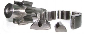
Pic.1 and pic.2
show common to all bent axis motors parts. You can see the shaft
assembly on the Pic.1. The pistons ARE replaceable, despite of what some
shops might tell you. It takes some work, you need to hammer out the
pistons (with a hammer, yes), and then to open a threaded holes inside
the brass caps to pull them out, probably gonna need to invent some
kind of a special tool for that, but it's completely doable. In case
you have some serious damage to the shaft prepare to pay (if you're the
motor owner) or charge (if you're the shop owner) some big euros for
the complete shaft assembly. Note the end cover on the pic.2, it's pretty much busted.
Pic.3, pic.4, and pic.5
show you one of the most common reasons these motors take a trip to a
shop, and often end up completely rebuilt. It is WAY too common
for hydraulics to malfunction due to clogged orifices. These three are
most of the times accessible without dismounting the motor from the
machine, and their "clogging" is pretty much detectable by checking the servo
pressures.
Pic.6
reveals a standard loop flushing assembly. Whenever you get a closed
loop motor with such a spool and a relief valve in the middle, you may
be sure it's for the loop flushing purposes. Note that this motor has a
single non-adjustable cartridge type flushing valve. Earlier models had
an adjustable one, very similar to the charge pressure relief valve
used in series 90 pumps. Some brands actually use an orifice instead of
a relief valve, making it a cheap and very compact assembly. The spool
centering sprigs break quite often, so make sure to check the whole loop flushing assembly.
Pic.7
show you the servo-piston, main spool and the feedback springs
arrangement. This is a size 160 motor, so the spring is divided in two
and has a guide in the middle, for it not to bend. Smaller motors have
a smaller single spring. I have seen desperate faces of some
"technicians" thinking "God! The position of the back cover was NOT
marked! What do I do?!" 1st - Read more! 2nd - The control and the main
spool are always to the min displacement side in these motors (NOT to
be confused with 51-1 series). Here we can see that the motor will
start at maximum displacement. When a force is applied to the spool it
moves left and sends oil to the left side of the servo-piston, moving
it towards smaller displacement (higher speed) and compressing the
feed-back spring at the same time, until the two forces equilibrium is
reached or the piston hits a mechanical stop.
On the pic.8
you can see the main control spool and the respective sleeve. Note the
two tank lines (in this case they connect to the motor's casing) on the
pic.9. It is through
these holes that the oil goes from the servo-piston to the tank. Some
versions, not this particular one, will have orifices in these holes,
so make sure to check them. I would advise you to take them out for
cleaning. A friend of mine once had to disassemble the motor
several times due to a small ball (actually a welding "spark") which
got caught (during a field-condition assembly) on top of one of these
orifices inside the sleeve, and was acting as a nearly perfect check
valve. The motor's control had a quick response one or two times (until
the air got out from the servo-cylinder), and then would take almost a
minute to go from maximum to minimum displacement, yet every time he
disassembled the motor and tested the spool assembly with an air gun he
would see the air passing freely through a seemingly unobstructed
passage. He found the problem after deciding to test the motor without
any orifices. Boy was he pissed at the welder working next to him...
Moving on to more interesting parts (pic.10).
Here we can see multi-function block (in the middle), pressure
compensator (on the left), and the proportional displacement control
(to the right, and also pic.11).
Let us first look at the displacement control. We know already
that in order to decrease the motor's displacement we must create a force
on the main spool. This assembly (pic.11) combined with the Sauer's standard torque motor (pic.12), and a special spool (pic.13) allow you to do this proportionally. Pic.11
shows you the oil passages, you can see that in this case the
torque motor is fed through an external connection. On some machines it
will connect to the charge pressure oil filter, many times to the
"before filter" port, thus practically forcing the torque motor to
function with unfiltered oil, so always check and clean the
"ever-clogged" screen, pic.12.
Mobile equipment get all sorts of oil contamination, I have seen these
screens get bent and deformed due to "extreme" clogging. When this
screen obstructs the oil your control stops functioning, and the motor
stays at the maximum displacement, rendering the machine slow.
Let us take a closer look at how the torque motor, or, as Sauer calls it, the PCP (pressure control pilot valve), produces the force to move the main spool (pic.13).
The pressures from the PCP are applied to both ends of the spool, one
acting directly on its top and the other passes through the side hole
and acts from the bottom, a pressure differential when the valve is
active will create force in one of the directions, obviously in this
case only the main-spool-ward direction matters. Now you can also see
that there is only one correct position of the spool, if you mount it
upside down, you will connect the torque motor outlets and there will
be no pressure differential and no force on the spool. The whole
assembly is mounted on top of the multi-function block and a small rod
is used to connect the control spool with the main spool.
Now let us focus on the multi-function block (pic.14),
here I already marked the holes, corresponding to the working lines (A
and B), maximum and minimum displacements, motor's case and the
servo-pressure supply. If you inspect the block carefully, you will see
that some circuit alterations are possible. For example it is possible
to plug the servo pressure supplying hole, and use an external servo
pressure source.
In this case the multi-function block is used to supply the servo pressure. It is done with this spool - pic.17,
which serves to select the high and low loop sides. This is an earlier
version. This spool has a small ball shuttle valve inside to select the
high pressure. So far I have seen at least half a dozen of those with
the ball seats broken, as the ball hammers them pretty heavily. The
newer design doesn't have the shuttle and uses a different spool
configuration to select the high pressure side, which can still be used
in the same "old" multi-function block. Make sure to inspect it.
I made the schematics (pic.26)
just to demonstrate that making YOUR OWN diagrams can be a useful tool
to learn hydraulic controls, a topic I am going to discuss in a
separate article. The original Sauer Danfoss technical pdf is
downloadable from their site, or here.
Have a look at pic.15 and pic.16. For this particular control this is NOT an orifice, this is a plug, On the pic.18
we see the pressure compensator defeat spool. Now what is Pressure
compensator and why is there a need to defeat it? Pressure compensator
is the system, that satisfies the transmission's torque demand by
increasing the motor's displacement when a certain working pressure
level is reached. Imagine our machine rolling on a plain terrain with
the motor at min. displacement (why at minimum? Obviously because we
told him to do so by supplying current to the control), then it enters
a ramp up and, of course, the working pressure starts to climb, when it
reaches the compensator setting it will increase the motor's
displacement to satisfy the increased torque demand, thus
automatically maintaining optimum speed and torque. Actually in
this case the correct name for this system would be Pressure
Compensator Override system (PCOR), as it is used to OVERRIDE the
electric displacement control signal.
Now if this system is so good and automatic, why is
there a need to defeat it? The answer is very simple - braking! Let me
explain it better. As you know, a closed loop transmission most of the
times doesn't need active braking, as the hydraulic braking provided by
the motor is more then enough. During deceleration the motor becomes
pump, and the pump becomes motor, as the machine's inertia is turning
the motor through gearbox and the resulting oil flow is trying to turn
the pump and the prime mover attached to it. Now imagine that
your pressure compensator would respond to the pressure rise in the
braking line and increase the motor's displacement?. You would start
braking with a 40 cu.cm motor and after the braking pessure passed,
say, 280 bar, ended up braking with a 160 cu.cm. motor, suddenly
quadruplying the flow in the braking line with a series of hilarious
consequences, like uncontrolled stops, broken transmission shafts or,
my personal favorite, overspeeded diesel engines and hydraulic pumps.
That is why we should always "tell" the motor which line to "pay
attention to" and which "to ignore", which is done by the defeat spool (pic.18), as you can see on the diagram (pic.26). Normally on a transmission like that the defeat spool pilot lines connect to the pump's servopistons.
By the way the defeat spool stopping rods (pic.18)
break pretty often, I have absolutely no idea why Sauer engineers would
resort to such lame and weak solution. Maybe the engineer who designed
this part was not German?..
Now as we know what the PCOR is for, let us have a look at HOW it works. Pic.19 shows you the connections, and pic.20 shows you the spool and the spring. Using the air gun test (pic.21)
you will spray yourself with hydraulic oil and also see, that
when the spool moves to the right (forced by high pressure), it
connects the high pressure to the max. displacement servo and vents the
min. displacement servo to the low loop side (pic.22). Check the schematics again if you have any doubts.
Many of these transmissions work with sophisticated
electronic modules, which control the pump, the motor, and even the
diesel engine. In such cases the motor speed sensing is needed, and
Sauer has a neat option of a magnetic ring and a Hall effect based
speed sensor. However the price of this simple sensor will make the
hair on your head move, and when you ask its price at your local John
Deere representative your hair will run away screaming! One of my
clients paid almost a 1000 eur. plus VAT for one of those, and he had
to, as the machine wouldn't operate correctly without the sensor (damn
them computers!). Would you like to know what is inside? Have a look (pic23, pic24, pic25).
A simple hall sensor, amplifier and logic circuits. There's a
place for another hall sensor, for the direction sensing option. Now
you can see that at least when you have a broken wire you can cut it
open and weld a new wire (pic.24
will give you an idea where to cut) instead of buying a new sensor. Note
that the circuit board is glued in the sensors body with some kind of
silicone. I was able to take this one out because it literally burned
(the machine had caught on fire), but to weld a wire you don't need to
pull it out.
My opinion about these motors? I like the rotary
group, very efficient, and we must admit that rotary group makes a
motor, as it is the part
which "makes it go", but I don't like the controls. I find
them over-engineered, there are simpler solutions, take a look at
hydromatik some twenty years ago, does the same stuff but has half as
many parts!... But series 51 work, and I see them do many hours on heavy
duty equipment, so I guess these motors are OK. Not exellent, just OK.
P.S. Nice manual on these motors (earlier series) here.