The following back-engineering example is devoted to the MS control for
Rexroth A4VG series closed loop pumps, used by O&K, Liebherr, and
probably other brand excavators for boom turning.
I don't get to see these often, and the ones I see
come from rather aged machinery, which makes me think these controls
are becoming obsolete, but there are several things about this control
module that make it a worthy back-engineering candidate.
First of all, you will find no technical
information on it because this isn't a standard control module (unless
you have access to O&K or Liebherr technical literature, of
course). Second, the quantity of the adjustment screws often
intimidates even the most experienced mechanics, leading those, who
aren't brave enough to tamper with the adjustments, to call for help
when adjustment are needed, and the ones, that aren't "fiddle-shy" or
"consequence-discouraged" , to call for help after
leaving the control ridiculously and, I would say, shamelessly
misadjusted... Third, I've seen experienced hydraulics technicians get
confused by the seeming complexity of the control module, which,
sometimes, would lead to wrong conclusions and many hours lost in vane
just because there's no clear understanding of its operation.
And, the last but not the least, regardless of it being obsolete, it must be back-engineered by the IH
for historical and educational purposes, because the principle used for
its operation is different from "standard controls" most mechanics are
used to, and is worth describing.
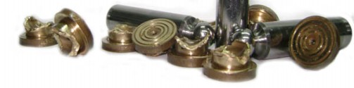
A word about the images. I made most of them last
time I dealt with such control (a couple of days ago), and when I came
home and looked through the pictures, to my great astonishment I saw
that I'd forgotten to take pics of the whole pump, and the
completely mounted control module. Too late for that now, as the pump
is toiling 24/7... I looked through my old pictures, and the best I
could come up with to show how a complete pump looks like is this
, (sorry for the poor quality), but I am not going to wait
for another of these to come by to finish the article. For
demonstration purposes I made the next best thing - a few schematic
images, just to show where the adjustment screws are, and how, in a
very simplified manner, such a control looks like.
The control is mounted on a typical A4VG Rexroth
pump, so I am not going to go into much detail about that. The pump is
equipped with all standard adjustments - charge pressure, two high
pressure cross-port relief valves, no pressure cut-off (you will see
why in a minute), the valve plate timing angle adjustment (or, as some
would call it, a pressure carry-over angle) and that's about it. I am
not going to discuss the adjustment of the angle here because this is a
topic for a separate article that is due pretty soon.
Now - the control's function. This control is not a
proportional displacement control, as most would expect, but rather a
proportional pressure control.
Its function is quite similar to the function of a variable
displacement pressure compensator control, only this one limits maximum
working line pressure (by destroking the pump at certain high pressure
level) in accordance to a pilot signal (coming from a joystick).
You will notice that it has no servo-piston mechanical feedback, but
has two high pressure feedback connections (which you don't see on the
pictures, sorry) to give the control necessary information about the
system high pressure. With this control the operator has a much more
precise control over the force, orbetter torque of
the boom rotation, and, combined with the rotary group reaction over
the swashplate (has to do with the above mentioned timing angle
and, again, is the topic for a separate article...) works as the pump's
input torque limiter, which is a good thing having in mind that the
excavator is driven by a diesel engine which has its torque limits.
Let us have a closer look at how exactly this MS control
for A4VG pumps operates. Take a look at the diagrams I made, here is the control module in neutral position, and here
piloted to one side, notice that I skipped drawing the rest of the
pump, which is a basic closed loop circuit. The spool 4, which you can
see here, has two machined flat faces (marked as crossed areas on spool 4 in the diagram),
which allow metered oil passage from the central groove (charge
pressure) to the side grooves (swashplate servo cylinder sides). When
the control is in neutral position, you will read charge pressure at
both sides of the servo-cylinder (something that can easily be
misinterpreted as malfunction by someone who is not familiar with this
type of control, by the way). When the pilot pressure from the joystick
is fed to one of the signal ports (Y1, Y2), the spool 4 moves to one of
the sides. Now the servo-cylinder oil supply is changed with onlyone side receiving oil through a strangulated passage (diagram). At the same time, both spools 1 and 2 (seen here, with the respective sleeves) are pushed to one side, venting to tank
the one side of the servo-piston, that is receiving metered (by the
spool 1) oil. When this happens, the pressure in this side of the
servo-cylinder drops to tank value. The originated pressure
differential strokes the pump. You can see on the schematics
that the spool 1 tank line opening, which is held open by the pilot
pressure coming from the X6 port, is being balanced by the high
pressure, acting on a smaller annular area of the spool 1. As the high
pressure increases, the spool 1 (and 2) shifts to the right (schematics)
and strangulates more the tank passage, thus allowing the pressure in
the servo-cylinder side to rise. When this servo-pressure rises, the
active servo pressure differential decreases and the swashplate moves
towards smaller displacement until a balance position is achieved. In
such a way the maximum possible system pressure will always depend on
the pilot pressure. Because the pilot pressure is fed through orifices
(which are not inside the control body, but are inside the external
pilot pressure fittings), it is possible to limit internally the
maximum pilot pressure and, consequently, the maximum high pressure,
which is done by the shuttle valve and the relief valve (schematics), and eliminates completely the need for the pressure cut-off system.
Unlike common closed loop pump controls, this one creates force in the servo cylinder not by increasing the pressure at
one of the servo-cylinder sides, but by supplying the same (charge)
pressure to both of the chambers in the first place, and then decreasing the pressure at one of the sides by means of a controlled venting. Understanding of this principle is very important for efficient troubleshooting.
Note that at low system pressure demands, due
to the fact that the spools 1 and 2 are centered by means of two
concentric springs (one of which is adjustable), the venting passage
size will depend on the pilot pressure, and so will the servo-cylinder
pressure differential, thus allowing proportional flow control and also
assuring "soft" starts, so very essential for massive boom movement.
In the same body that houses the spool 4 there's another spool (seen here). As you see on the schematics
it opens an additional connection between the servo chambers below a
certain high pressure level. When pilot pressure is present, the
position of this spool doesn't influence to a great extent the function
of the control, as the spool 1 and 2 close and open the controlled oil
leak according to the high pressure feedback, overriding the oil demand
change when the spool 4 is in the "open" position. If you put the pump on a
testing bench and pilot it, you won't see much difference between this
spool spring blocked or completely loose. But you will see a lot of
difference during the destroking stage. The adjustment of this function
will alter the "braking curve" of the pump, because when the additional
oil passage between the servo-chambers opens, the pump destrokes faster.
If you loosen the adjustment - the stops become "softer", if you turn
it in - more abrupt. This function can be eliminated/activated by
removing/installing a small plug here.
Pilot sensitivity of this control is
adjustable, with the normal setting lying between 160 (soft response)
and 200 (violent response) bar high pressure at 20 bar pilot. To adjust
it on an excavator all you have to do is to brake the boom, install
pilot pressure and high pressure gauges, push the joystick to supply 20
bars pilot, and adjust the respective screws on the spools 1 and 2 to
limit high pressure to 160-200 bars. Note that if you want to adjust
the pump's high pressure relief valves (normal setting around 430-440
bars), you might have to rise the pilot supply to around 50 bars.
Now you can see what happens when you have the high
pressure feedback hoses switched (I personally have seen this happen
more than once!). Instead of de-stroking the pump at certain high
pressure, the control will be stroking the pump with all the
consequences...
Make sure to check the shuttle valves condition (here and here), they get pretty worn and when they break, the ball can easily damage the cast body beyond repair.
I sincerely and truly hope that this back-engineering tale has showed you once again that no pump control is to be feared.
My opinion about this control? Sophisticated? Yes! Functional? Yes! Aristocratic? Yes! But... performs almost like a dead simple direct operated DG hydraulic control, so is there really a need for all that complication?...