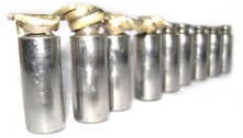
This is Linde BMV-105 variable displacement motor with a simple
proportional displacement control. It is not that this motor has a
special control module or something - no - it's quite simple. It
possesses, however, what I like to call "the other way round"
adjustments, making it the perfect example of how things in hydraulic
components often are the opposite of what they seem, and a
good illustration to my previous post on left adjustments.
When you look at it
- you see nothing but a normal bent-axis type hydraulic motor, which
has two adjusting screws and a couple of pilot lines. On the first
glance everything is standard and pretty much alike other bent axis
motors. Let us look now at the adjustment screws one by one.
First - the displacement limiter. Again, from the outside
you can see that it is a robust screw situated on the max. displacement
side of the end cover - in a classic design of a bent-axis
variable displacement motor this would be a simple mechanical stop that
limits the maximum displacement. However in this motor it limits the minimum displacement. You can see why here - the stopping screw has a head that works inside the servo-cylinder - the more you screw it out - the bigger is the minimum displacement of the motor.
Now - the proportional displacement control. This is a simple control, based on the good old spring feedback design. This particular module was using the Y port (check out the schematics)
to override the X port signal when needed, however on most motors I've
seen so far the Y port is not used (it is plugged and is internally
connected to the motor case). Now if we consider the control threshold
adjustment - we'll see that screwing the adjustment screw in actually de-compresses the spring, and lowers control start pressure.
As you can see - the motor is a perfect example of the "other way round" adjustments. The stopping screw at the maximum displacement side is actually the minimum displacement limiter, and if you want to increase the displacement control threshold - you must turn the adjusting screw out!
The rest of the motor is trivial. It has the loop flushing relief and shuttle,and the rotary group is, well, just another Linde-ish rotary group.
One thing I would really like to ask Linde engineers - where the hell are the servo-pressure measuring ports?!!
When you troubleshoot a closed loop transmission sometimes you need to
confirm whether your variable displacement motor is in the max. or min.
displacement, which is done through servo-pressure readings . In case
of this motor the only thing you can read is the model plate - it says
"Linde BMV105" - not a helper, is it?
Here's a tip for you - if you are not sure whether
your BMV 105 is in the max displacement (for example when you see that
you closed loop transmission doesn't give out the torque you need, and
you suspect motor displacement issues - screw the min. displacement
stopping screw all way out - by doing so you mechanically bock the
motor control at max. displacement, eliminating any influence from the
displacement control module.
This series is rather old, so we don't get those
often these days. Like any other Linde creation - these are very high
quality built motors, with remarkably over-priced spares and design
that can be characterized as "different for the sake of being
different" and "over-engineered for the sake of being unique". Are they
good and reliable? Yes, they are, very much! Would I want one in my
machine? No, I wouldn't, and I'd replace one with a Sauer or a Rexroth
motor if I had. This is subjective, of course...