Wow! What did I get today?! An original Liebherr LPVD 064 pump? Sweet!
I don't have any literature on Liebherr pumps, so this is going to be a
good example of mind reigning over matter.
Pic.1
shows how it ACTUALLY came. I am so used to getting dirt-in-oil mixture
covered pumps, that this one made me blink to see if I was dreaming!
Intimidating at first sight, these pumps are pretty easy to
disassemble, the only tricky thing being a small stopping screw which
holds a pin connecting servo-piston link to the swash-plate. To unscrew
it you'll have to remove the drain plug (or fitting), take a flashlight
and peek inside the casing through the drain port, you'll see it.
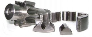
On the rear of this pump you find a very common gerotor-type pilot pressure pump (pic.2). Take a good look at pic.3,
this is NOT broken. I have seen one of those replaced because the
technician thought there was a chunk missing. Boy was he surprised to
see the new one "broken" in exactly the same manner! Well, we live, we
learn...
Moving on. First of all let's dismount the controls from the body (pic.6).
As they are pretty much identical, only one outer part being different,
let us concentrate at this point on the easier one (the one which
doesn't have an extra connection.) It has a feedback lever, two
adjustment screws, and a solenoid. The holes on the central part of the
pump (pic.4, pic.5)
have the same pattern for both the front and back pumps, which again
tells us that most likely the two controls are functionally identical.
The next step is the most important - to define the
functional holes in the central body, which is not hard at all but NO
mistakes can be made at this point, as it may lead to a false
understanding of the control. So take out your air-gun, permanent
marker, goggles (yes, it's gonna get messy!) and advise the
audience to stay way back. The following procedure is simple - you pick
a hole, blow into it with your air-gun and see what happens next. When
you are POSITIVE about a hole you mark it - that's it! You should also
define the servo-piston configuration (where the small and the big
areas are, does it have a spring, does it have stroke limiters) and
which way it moves for the maximum and minimum displacements (pic.4).
OK, now we know the body connections and can move on to
the control itself. First of all let's mark it according to the body
marks and have a closer look at it (pic.7).
I always test the controls with air. The objective here is to define
the starting point, i.e. if the pump starts in max. or in min.
displacement. In this particular case it is very easy to see that this
pump will start at min. displacement, as when we blow inside the P port
(most likely place to get servo pressure in open circuit pumps), the
air is fed to the min. displacement servo port. There's a check
valve inside the P (high pressure connection) hole (pic.8, pic.9).
We know that there is a side connection that goes to both of the
controls, and after seeing the check valve, might suspect some kind of
boost pressure system. After further inspection we find another check
valve (pic.14), in the
pass of the oil coming from the side connection. At this point I have
no doubts that this is a boost pressure system, a common thing for pump
systems starting at min displacement, as there's no sufficient servo
pressure in the pump's outlet when it's at min. displacement,
especially when min. displacement is close to zero. In these cases a
boost (or a pilot) pressure pump would normally feed the servo pressure
to the pump's control, thus guaranteeing its fast response at all
times. The check valves are obviously needed to prevent the high system
pressure from entering the low pilot pressure side and the pilot oil
from getting into the pumps outlet when the pump's at zero. Look at the
LPVD 064 circuit schematics I made, it's pretty self explanatory.
Now let us go ahead and take the solenoid out (pic.10).
Here we can see an interesting detail. Liebherr engineers connected the
boost pressure line with a plate between the solenoid and the control's
body via a small orifice (pic.12). The plate itself has two oil passages and allows the oil coming from the orifice to flow directly to the pump's case (pic.11).
I would guess that this is for lubrication/refrigeration purposes.
(them solenoids sometimes get really hot!) and, maybe, for continuous
oil renewal inside the solenoid (the nucleus is wet).
Let's check the spool behind the solenoid. I
usually try to simulate a spool's movement with my finger, blowing with
an air gun at the same time into the servo-pressure supplying port. In
this case it is also very easy to see that there is a spring-connection
between the spool and the feedback lever, as when we move the lever,
it takes more effort to move the spool. After the air test we know that
this is the main spool (I call the main spool the spool, that directly
controls a pump's displacement), pressing on its end with a finger
diverts the oil from P to max. So we have here a solenoid controlled,
proportional, positive displacement control. The solenoid receives
current and pushes against the spool, thus connecting the servo
pressure to the max. servo port. As the swash plate moves towards the
max. displacement so does the feedback lever, compressing the feedback
spring at the same time. Finally the solenoid force and the feedback
spring force will reach an equilibrium point and the servo piston
movement will stop. The stronger the current, the bigger is the force,
hence the further the servo will move. A classic proportional closed-loop control
arrangement.
Let's have a look at where the test fitting is connected (pic.13).
Not hard to see that it's connected to the max. displacement servo
pressure. A useful point to determine whether the pumps swash plate is
tilted at the moment.
To dismount the feedback system we must take out the pin (pic.15) and the adjustment part (pic.16). The complete feedback mechanism is on the pic.17.
Here we can see that the adjustment screw pushes the small spring which
in turn pushes the main spool via the shaft that goes through the
feedback. This would be the starting point/sensitivity adjustment. The
stronger the spring adjustment the bigger current you will need to make
the main spool move.
Here we see that the feedback doesn't continue (pic.18).
It means that there's no torque control, at least mechanic, as with the
electric proportional displacement control system it is easy to
establish the torque control electronically, which is most probably the
case of this machine.
Let's try to see what is the function of the upper part of
the control now. Even before opening it I would already imagine it's a
pressure limiter, as nothing else makes sense, but it's always a good
practice to check EVERYTHING. Here we have the adjusting screw part,
the spool with the small rod in it, acting as a piston, and a plug with
a spacer shim (pic.19).
Normally I always do the air test. Most of the times shop air pressure
(5-6 bar) is enough to see which way a spool would move. In this case
we see, that air from the P will press on the rod inside the spool,
thus pushing the spool against the spring. This is also a great example
of the two biggest dangers of such air tests. First -
parts lost during disassembling of a control (take a look at the shim
at pic.19, if you are
not careful, it might fall and get lost as you take out the plug, and
you wouldn't even know. When I pulled the plug out it fell on the floor
and I had to look for it) and second - parts "Gone With the Wind", the
most dangerous part if you are not careful or have little experience.
Check out pic.20, if
you have the plug removed and you blow inside the P port without your
finger closing the plug hole, chances are you will never find the small
rod, and if you don't hear it fall, you wouldn't even know it was
there, which will lead to the control malfunction. I actually have a
ball valve insatlled in my air-gun to be able to control the air
strength when needed.
A few more air-gun stunts and we can see that when the spool (pic.20)
moves (we know already that it is the high system pressure that moves
it), it vents the max servo pressure line to the tank, which definitely
means that this is a pressure limiter. See? Very easy!
Now what about the other control (pic.21)? A quick inspection shows that it's basically the same control, with only one different part (pic.22), which has a pilot connection. Let's open it (pic.23).
Here we can see a small piston with a spring that holds it in the back
position, and two other springs acting on the same small shaft (goes
through the feedback to the main spool) we saw before (pic.17).
The smaller spring is pressed by the piston, which means that this is a
two level sensitivity adjustment, when you have pilot signal pressing
the piston, both of the spring act on the shaft, when you have no pilot
pressure, only the bigger one does. Why is it needed? My guess here,
without seeing the machine itself, is it's used for low
speed regimes. Supplying the pilot pressure to this connection will
decrease the control's sensibility to electric current, thus making the
functions slower. Normally most mobile machines have some kind of a
tortoise/rabbit switch, so I'm guessing this port is used for this
function.
Every time you see such an assembly (pic.22) you should suspect a two level adjustment, triggered by a pilot signal. It's quite common design used in many types of valves.
In my opinion, this is a good pump, with German
quality written all over it. I don't get them often at my workshop, but
I can tell it's a reliable design, which probably could be a little
simpler, though. I am pretty sure that when those pumps have many
hours, they work all right, but leak lots of oil to the outside.
Overhauling might be expensive for this brand (at least at my workshop,
as this is not a common brand here).
Once again the LPVD 064 diagram
(my version), note that it's a bit simplified (the control sensitivity
part doesn't show the second spring). This is just one example, there
are many other control options for these pumps, all based on similar
designs.