Many thanks to Doug Hanson (don't forget to visit his blog), who helped me with useful information about these pumps and Komatsu's jet sensors.
This article features a small video, showing pressure readings during the test of the described pump, and also the pump's hydraulic schematics.
When I described the simple
third generation Komatsu pump, I promised to give the topic a
continuation in a "couple of weeks", which, unfortunately, transformed
into a "couple of months"... Well, better late than never. This
back-engineering session will be focused on a more complex control of a
Komatsu OLSS pump from the vintage third generation, (at least the IH version of it).
In the previous article
I described how a simple proportional displacement control in these
series works, and what adjustments it has, further in this article this
part of the control (the positive displacement control) is referred to
as the PDC.
You can see that this particular pump is no different, and has exactly the same PDC as the simple
one. The only difference is the pilot pressure measuring port, which
ends with an external fitting rather than a simple plug. I have no
information on how this connection is used on the actual excavator, but
several ideas come to my mind, like limiting the pilot pressure to
limit the maximum displacement, or using this feature as an emergency
override? These are only guesses, though...
Before going into the pump's control, some light must be shed on the so very mysterious OLSS system matter.
What is this OLSS and what are its main parts?
The OLSS, standing for Open center Load Sensing System, is the name that
Komatsu gave to a hydraulic system used in some of its excavators. In
contrast to classic load sensing system, which uses a closed center
directional valve, and senses load induced pressure, in this system an
open center valve with a separate central gallery (just like a normal
distributor with a carry-over) is used in combination with the
so-called jet sensor valve, connected to this very gallery.
Unfortunately, I have never opened one of them jet sensors, so I can
not give you a detailed description of its parts, but its function is
very simple - it transforms flow into pressure signal - the more flow
passes through the valve, the higher the pressure signal is. Then this
signal is fed to a variable displacement pump, equipped with negative
displacement control - the higher the signal pressure - the lower the
displacement. This is the simplest layout of the OLSS.
How does it work? When the spools of
the distributor valve are in neutral position, the oil is redirected
from the valve inlet to the central (carry-over) gallery, and,
consecutively, to the jet sensor, which senses the flow and puts
out a pressure signal that de-strokes the pump. The system is in
stand-by mode, the pump is at its lowest displacement, with a small
amount of oil passing at low pressure through the jet sensor. When a
spool is moved, the valve's inlet is disconnected from the central
gallery, thus reducing the flow through the jet sensor and,
consequently, reducing the jet sensor pressure signal, which increases
the pump's displacement. In other words, the OLSS system is based on
sensing the flow in the carry-over line, and giving the main pump the
signal to increase displacement, when the flow in the carry-over line
decreases.
Now a little bit more about the jet sensor. In
theory, the simplest valve to transform flow into pressure signal
is an orifice. In case of the jet sensor, the story is a little bit
more complicated. Due to the fact that this valve can be subject to
sudden high flow discharges, when the spools are returned to the middle
position and the pump is still at its full displacement, it is equipped
with a low pressure (around 17 bars) limiter valve, capable of handling
high flow. Then, as the jet sensor tank line is subject to pressure
changes, the jet sensor supplies not one pressure signal, but two - one
from the orifice side, and one from the tank line side, which are then
fed to the pump displacement control, where the signals are connected
to opposite equal areas of the same control spool, thus ensuring that
the return line pressure fluctuations don't affect function of the
displacement control. I managed to get my hands on a shady cut-view
image of a jet sensor from a PC 200-3, which suggests that the flow
sensing part is something more than just an orifice, but due to the bad
quality of the image I couldn't deduce much more, although I can think
of at least a couple of possible layouts for the same function.
Once again, with an example? Ok,
but the example is from my head, meaning that it is only my vision of
how such a circuit might work... Say, we have a 100 liters per minute
pump with a 0-15 bars negative displacement control and a distributor
with a carry-over. We mount a 2 mm orifice in the carry-over line and
connect the pump's pilot line before the orifice - and there you have
it - a basic OLSS circuit to teach and learn! When we turn on the pump,
with the distributor lever in central position, the pump flow is
directed to the orifice in the carry-over line, the pressure before the
orifice (and in the pump's pilot line) will start to rise and at
certain flow rate an equilibrium between the pilot pressure and the
flow rate will be reached. Let's say the equilibrium is reached at 8
liters per minute through the orifice and the resulting 14 bars in the
pilot line - the stand-by low displacement mode. Now, let us connect a
needle valve to the distributor work lines (to simulate load). When we
move the spool, the moment the spool starts metering the flow through
the carry-over line and divert it to a work line, the pressure signal
in the pilot line will start to decrease, resulting in increase of the
main pump's displacement. Now let us move the spool to a position,
where we have around 5 liters per minute through the orifice, resulting
in 7 bars pilot pressure and 50 liters per minute through the needle
valve - the OLSS at work, partial displacement. Now, if we start to
close the needle valve, and increase the work-line pressure, the flow
to the carry-over line, which is now being metered by a very small
opening of the spool groves, will also increase, resulting in the rise
of the pilot pressure and consequent de-stroking of the pump. If we
maintain the position of the spool unchanged, every raise of the load
pressure will result in a new lower flow equilibrium. If we look at it,
this system actually works like a torque limiting control during the
partial displacement transition period. If we continue to close the
needle valve, it may be possible to reach certain high pressure level
when there will be zero flow through the closed needle valve. To shift
from this equilibrium point and to rise the work-line pressure a spool
movement will have to be made. Finally, when the spool groves close the
connection between the inlet and the carry-over gallery, we will have
zero flow through the orifice and zero pilot pressure, which will
result in full pump displacement. If we drop abruptly the lever to its
central position, we will connect the pump on full stroke with a 2mm
orifice, creating a nasty pressure spike, and, probably, ending the
experiment with a kaboom, and at this moment we'll wish there'd been a
pressure limiter in the orifice line....
Ok, so what's the big idea? Well, just
like the normal LS, this system provides low-displacement stand-by
mode, which increases the life of the pump and decreases stand-by
losses. And, just like the normal LS, it allows the pump to be used at
partial displacements when slow movements are required, thus reducing
wear and fuel consumption. But, if I were to compare the two systems, I
wouldn't be able to say which one is better. They are just different.
One of the advantages of the OLSS is the fact that
it uses only one valve (the jet sensor) and one signal line (well, two,
actually, but in ideal zero return line pressure situation it would've
been one...) to control the pump - no multiple shuttle valves,
orifices, LS line venting valves and what not - common to classic LS
circuits. But then the control module of a closed center LS pump is
simpler, and, therefore, is less prone to malfunctions, and I would
guess that for the OLSS system to demonstrate best results a specially
designed distributor must be used, with the ability of precise flow
metering between the inlet and the central (carry-over) gallery.
The classic closed center LS offers the built-in
ability to maintain the speed of the actuator constant in changing load
conditions, while the OLSS doesn't. But then again, the built-in
ability to function as a torque limiter, may be, actually, a desired
feature. At this point another question pops up (Doug
gave me the idea) - why the hell did they call this system a Load
Sensing system? There's no real load sensing here, is there?..
Anyhow, when well adjusted, this system
performs smoothly, which makes it one hundred percent functional, and
all of those OLSS Komatsus out there are the living proof to it.
The most important thing is to understand how
the OLSS works, so that when you fiddle with it, you don't do it on the
"blind" basis...
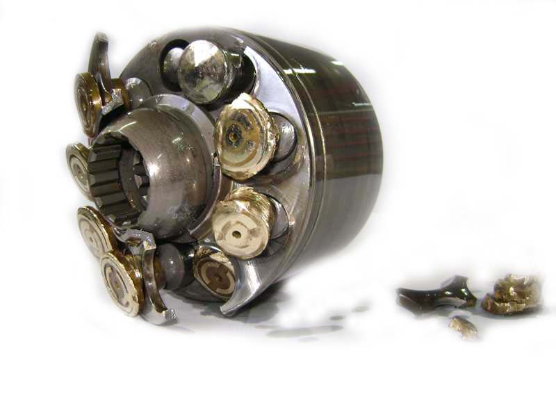
Now, about the pump itself.
As I have already said above, what we have here is the
same PDC pump, with a bunch of controls on top. As we already know how
the PDC functions (from here),
let us focus on the rest, because what Komatsuneers created here, is
actually an open loop control (open loop means that it has no feedback)
system, which uses several simple pressure reducing valves, connected
in series, to control the PDC pilot pressure. If you look at the
schematics, you will see
that the pilot/servo pressure signal (coming from an external source,
on some pumps there's a small tail pilot pressure pump and a pressure
limiter for that purpose, but not on this one) first passes through the
TVC valve, mounted on the rear pump control (TVC is the name
Komatsu gave it), which is a pressure reducing valve assisted by both
front and rear pump outlet pressures and the solenoid, and functions as
torque limiter (sum of both pumps). The pressure signal, resulting from
the TVC valve, is then fed to both controls (front pump control is fed
through the S shaped metal tube, there's also a plug
where you can take this reading), where it passes the CO (named by
Komatsu) valve, which works as high pressure cut off valve, and can
have a hydraulic override option (I didn't draw it on the diagram, to make it simpler, but the actual pump has this option,
which is most probably used in heavy excavating regimes, like a power
boost function), then the pilot pressure passes through the NC valve,
which modulates the pilot pressure in accordance to the delta P of the
two signals supplied by the jet sensor, thus working as negative
displacement control, and then, finally, the pilot pressure enters the
PDC.
As you can see, the control is rather simple. It is
equipped with leak free adjustments which can only be adjusted within a
rather narrow range. For example the pressure cut off has a minimum
setting of around 230 bars (was set to 320 bars). This pump's control
module presented notorious hysteresis, the PDC had working range
of 4-19 bars, minimum displacement was 15 cu cm., maximum - 125 cu cm.
Signal lines delta P of 12 bars was enough to put the pump at min.
displacement. The test itself is quite interesting, because there's a
whole lot of pressures you can control to see its function. I made a
short video of the test, purely for educational purposes, which will be interesting only for those who like to go into detail.
To recapitulate - the pump is equipped with a torque
limiter with an electric threshold override, pressure cut off with a
positive hydraulic override, OLSS negative displacement control
(operated by delta P of two pilot pressures). You will find the
adjusting points on the pictures.
Should you have any questions or some additional info on the OLSS matter, please, feel free to contact me.