
Insane Hydraulics
Bold and audacious blog about fluid power
For the last couple of months, I have been experimenting with a pressure transducer cell connected to a "proper" analog-to-digital converter, and I must say the experience has been super educational. Inspiring even, in the sense that it gave me some pretty cool and, dare I say, "revolutionary" ideas!
This, of course, means that I will soon be inviting you to follow along with the development of this undertaking via a series of articles, but before I embark on the new journey, I must do justice to my last DIY hydraulic-electronic project - the Wireless Pressure Transmitter - and overview the details of its hardware.
In case you don't know yet - some time ago, I did something that every hydraulic tech who ever saw an industrial pressure sensor thought of doing at some point - I connected a couple of such sensors to Bluetooth modules and started using them as wireless pressure gauges - and after iterating through a series of "prototypes of prototypes" I ended up with these bad boys:


Despite the obvious crudeness - these gadgets work, I still use them at least once a week, and they have earned their weight in gold multiple times! But, as is the case with every electronic device, they are hopelessly outdated now - the design based on the Silicon Labs BLE (Bluetooth Low Energy) module that uses an 8-bit 8051 CPU and requires a special scripting language for programming the firmware can not be reproduced anymore - it simply wouldn't make sense. Modern modules offer more options and computational power, and - what I love the most - a much better development experience because the firmware can be written using the good old C.
But this does not mean that my wireless pressure gauge design was all bad - I would say that it's only half-bad, and in this post, I want to reveal and discuss the hardware part so that if you ever decide to employ an industrial sensor with a standard analog interface (e.g. 4...20 mA or 0...10V) in your battery-powered DIY solution for monitoring whatever you need to be monitoring - you have a starting point.
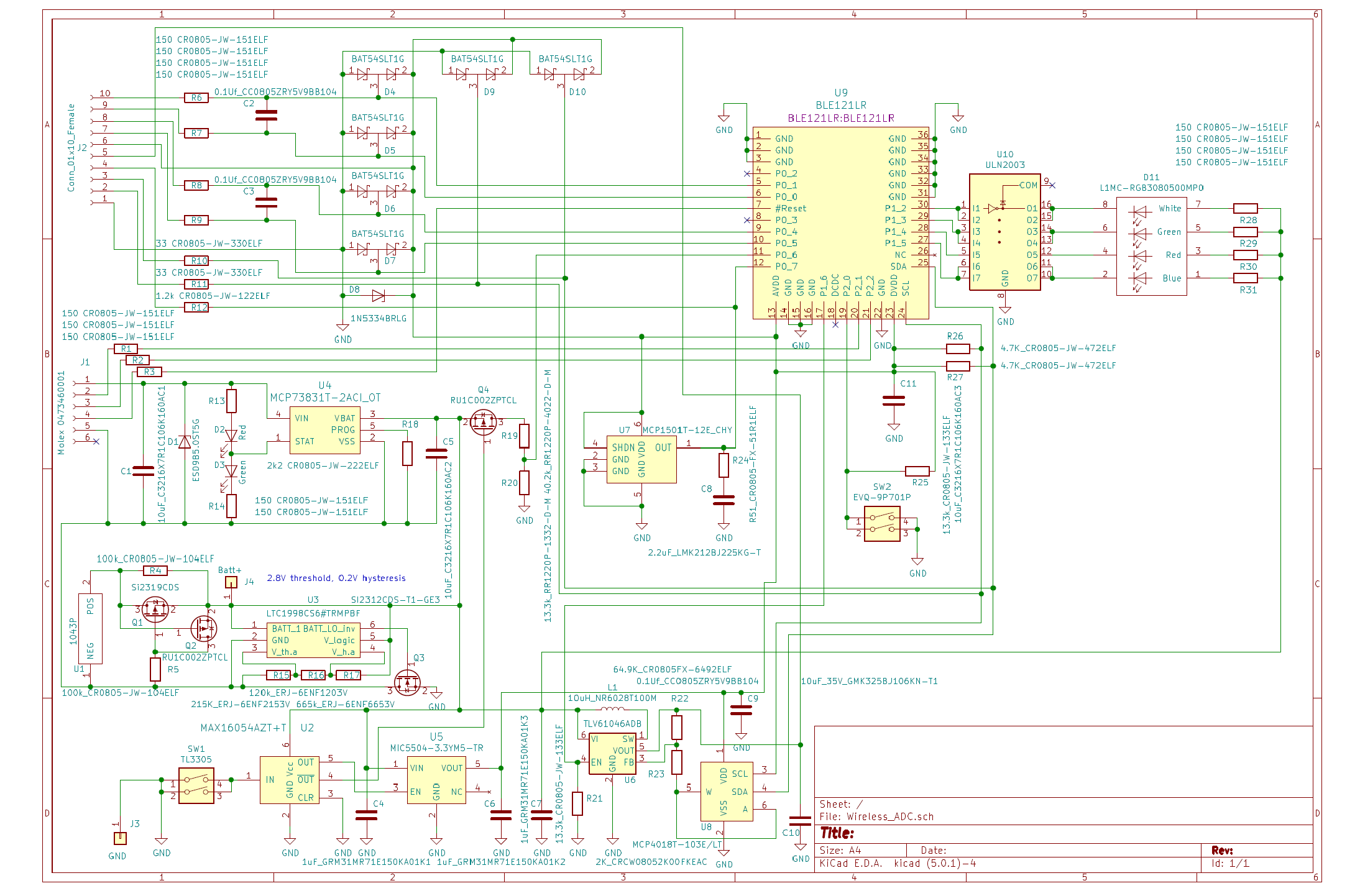
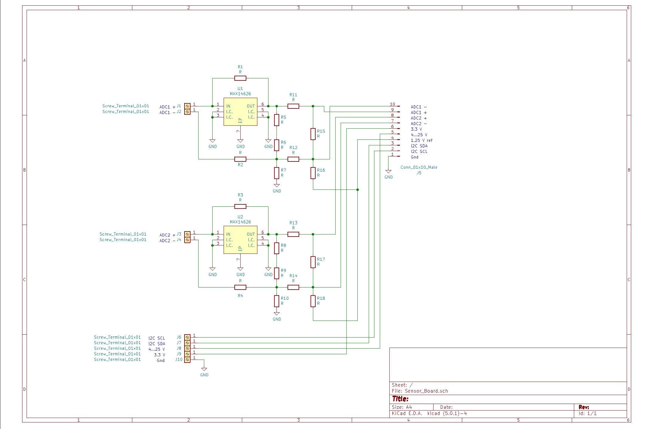
As you can see in the pictures - I separated the sensor-connecting part from the BLE module into two independent PCBs and used a custom-built magnetic connector with gold-plated contact pads and pogo pins to connect them. Here are the electric diagrams for the module and the sensor board, and some pictures (if you followed the project, you are probably already familiar with these details):
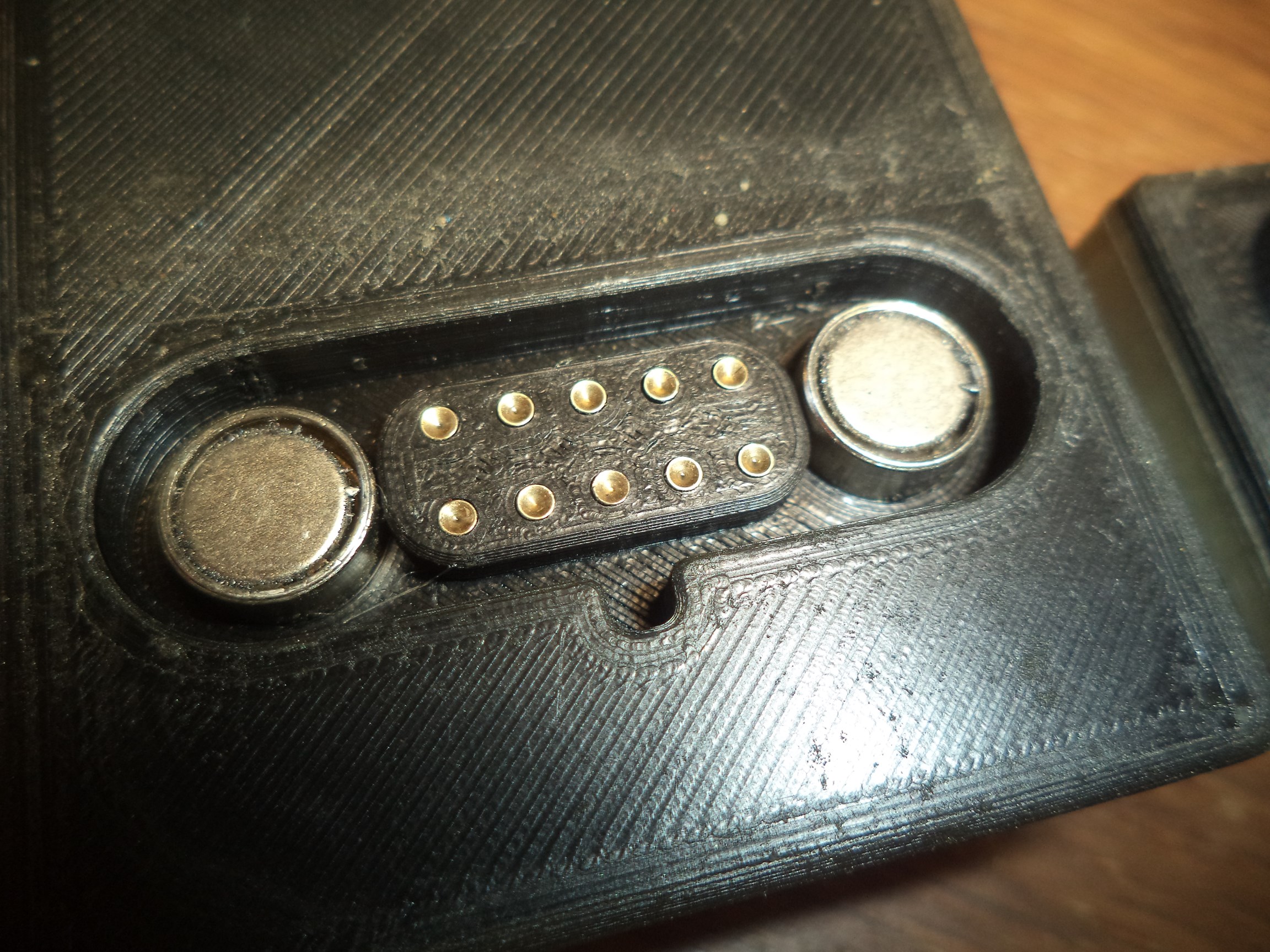
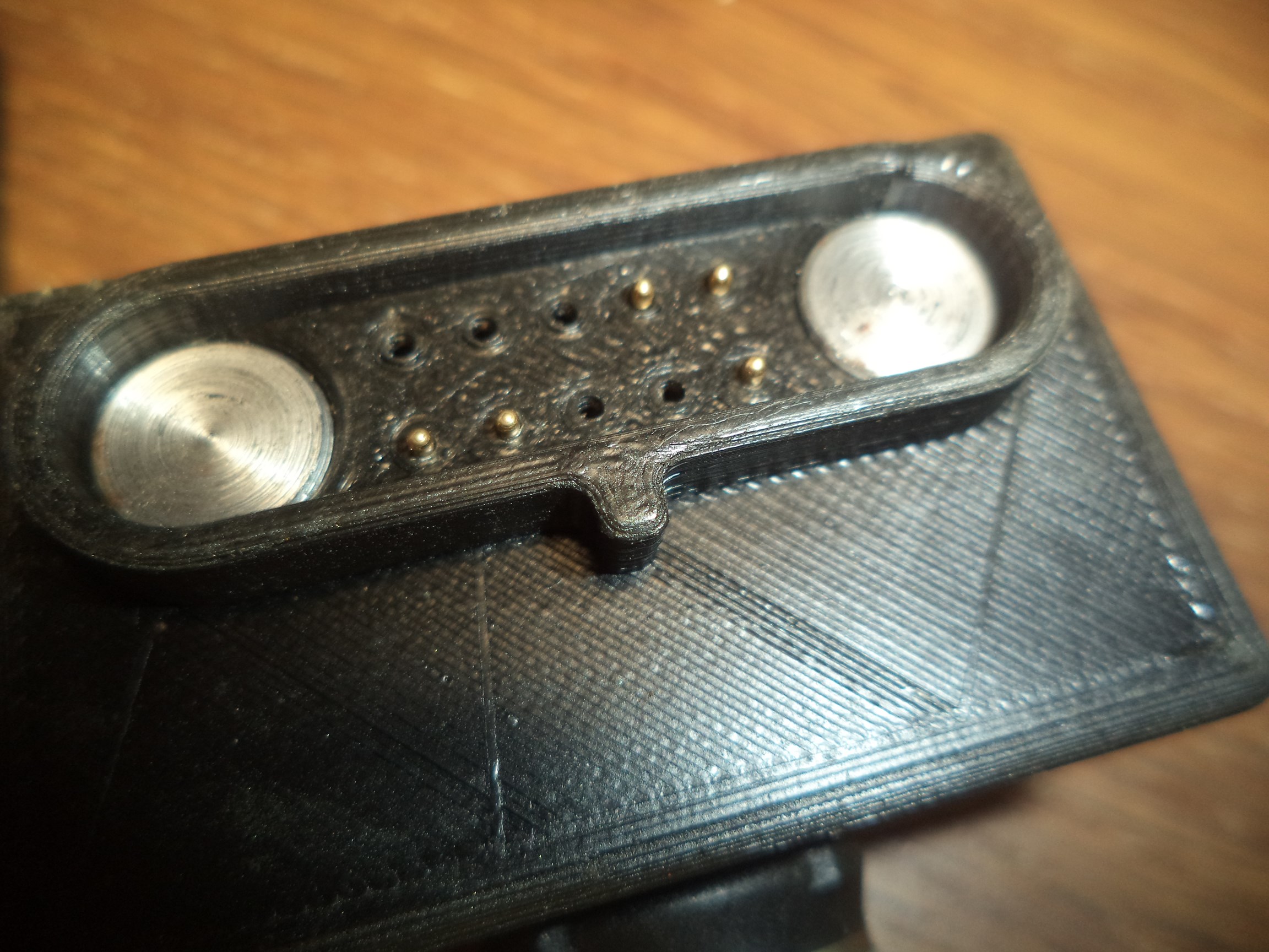
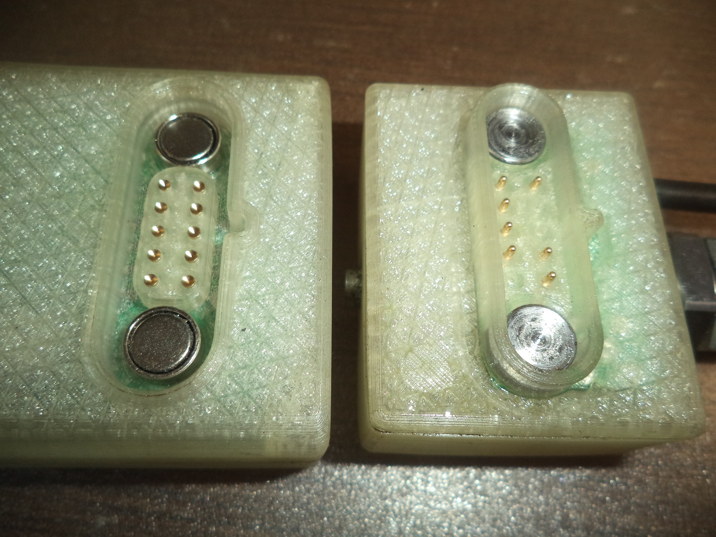
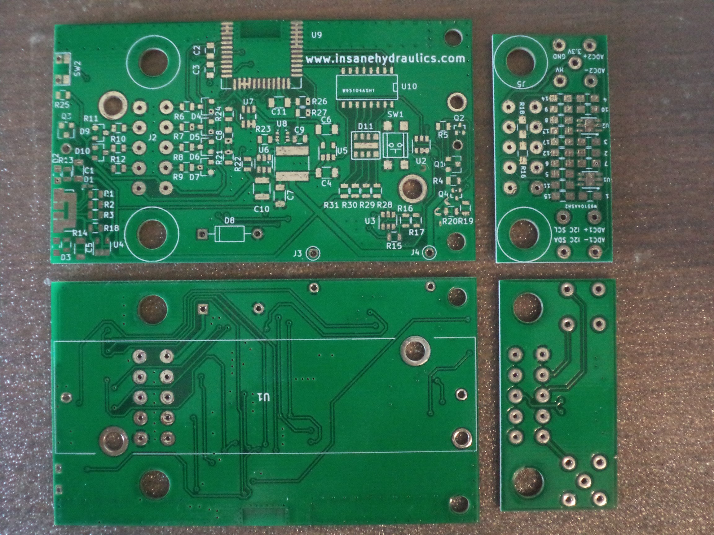
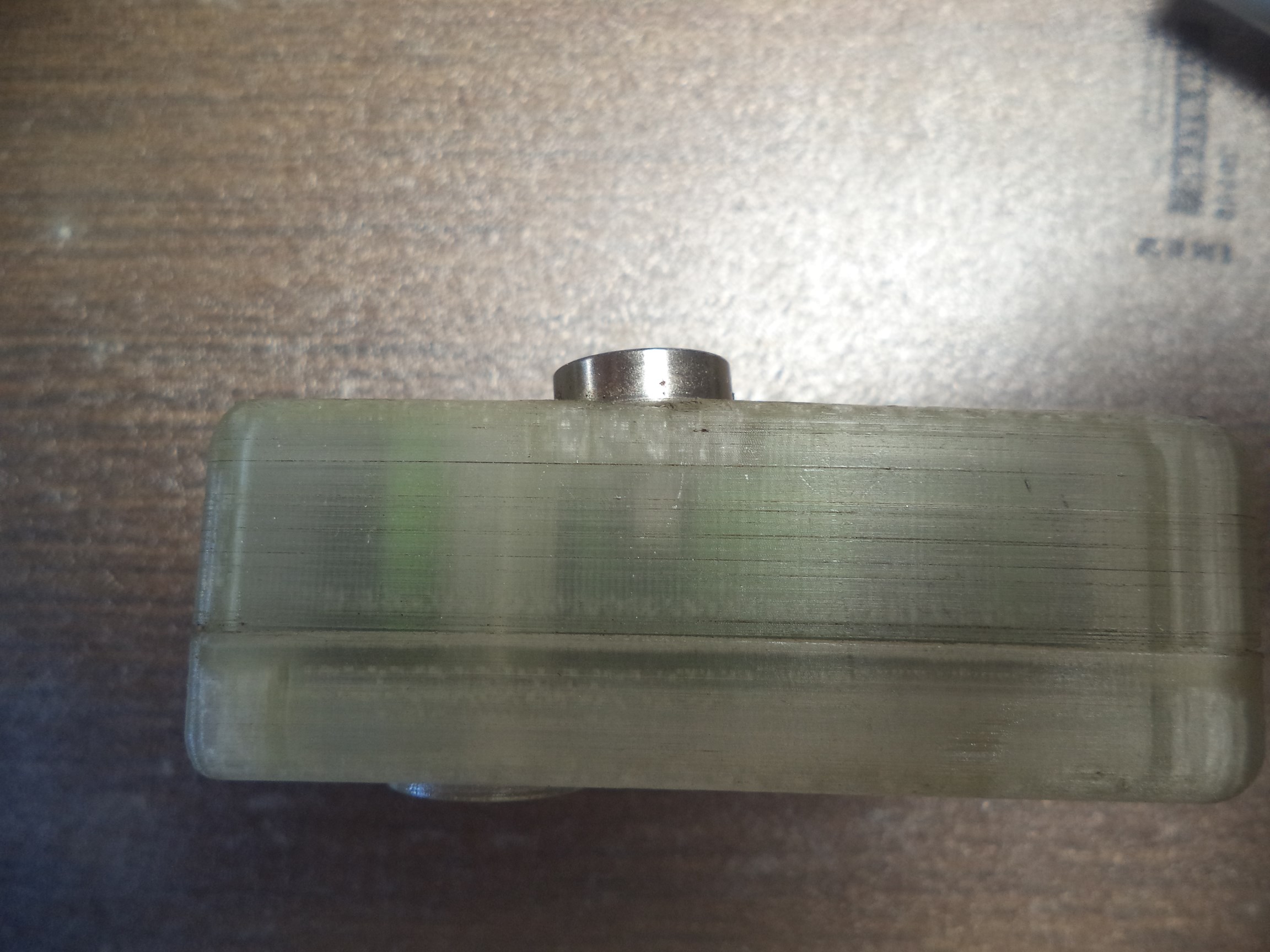
The idea behind the quick connector was to have a wireless ADC to which I could quickly snap different kinds of sensors/cables - but... in almost five years of intense use (I am honestly blown away by the fact that this DIY solution soldered on a hot plate and placed in a 3d-printed enclosure has lasted that long) I never used this feature. Not once! I came to the conclusion that the quick connector is completely unnecessary, and in retrospect - I regret wasting time on designing it. The simpler the better! Furthermore - the connector turned out to be unreliable, too - even with the gold-plated pins and pads I noticed that occasionally wiggling it would offset the reading - which is unacceptable for a pressure-measuring instrument. So - if you liked this idea - ditch it! It's no good!
On a side note - the 3d-printed PLA body is resistant to oil but not to heat - if you look closely at the magnets on one of the bodies - you'll see that they are crooked - I once "glued" the transmitter on top of an especially hot tank, and the body literally melted!
But let me showcase the good stuff now.
First and foremost - this is a device that uses a removable 18650 Li-Ion battery.
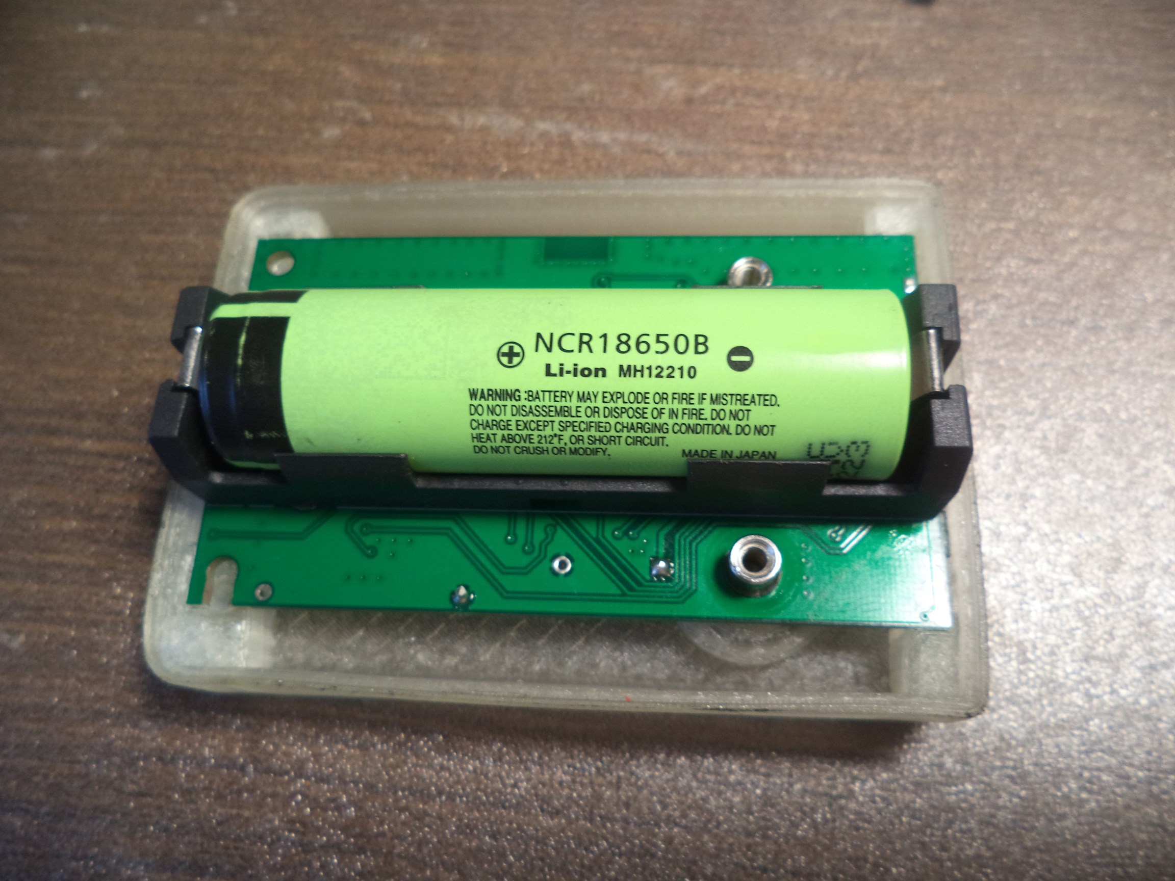
The key word is removable - which means the battery can be inserted the other way around and fry the circuit - and if you know what 18650 cells are capable of - you'll agree it's no joke. I knew for a fact that sooner or later I would be inserting the battery the wrong way - which is why I used the (very elegant, IMO) solution that protects the circuit from reversed polarity and allows charging at the same time - it only requires two p-channel MOSFETs and two resistors - Q1, Q2, R4, R5 in the schematic. The idea is not mine - I took it from this application note, kindly provided by Analog Devices. If you ever opt for using a removable chargeable battery in your design - use it, it's awesome!
The second good part would be the one that converts the 3.6V from a single Li-ion cell to a higher voltage typically required by industrial sensors (12-24 VDC). The voltage converter is based on the TLV61046A boost converter (U6) and the MCP4018T I2C digital potentiometer (U8) for regulating the output voltage. This solution is extremely compact and requires only six external components aside from the booster and the pot to operate. It is quite efficient, too, so if you ever need a higher (and adjustable) voltage from a single battery cell (within reasonable current limits, of course, but sensors rarely go over 20 mA) - this solution is perfect. The only thing you should be aware of is that the booster should be disabled before selecting the pot's resistance - if you don't do this the booster will default to 12VDC output during the switching of the voltage divider.
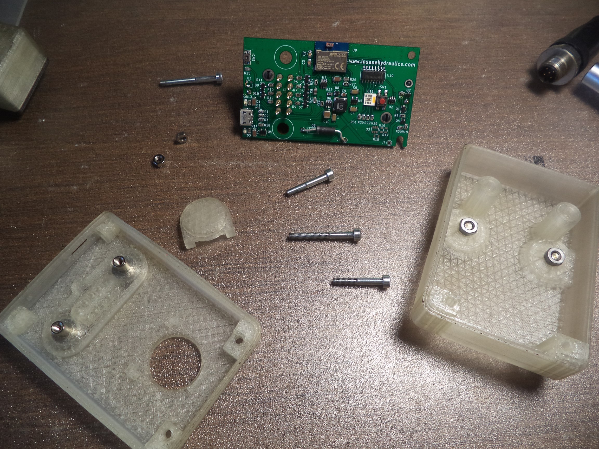
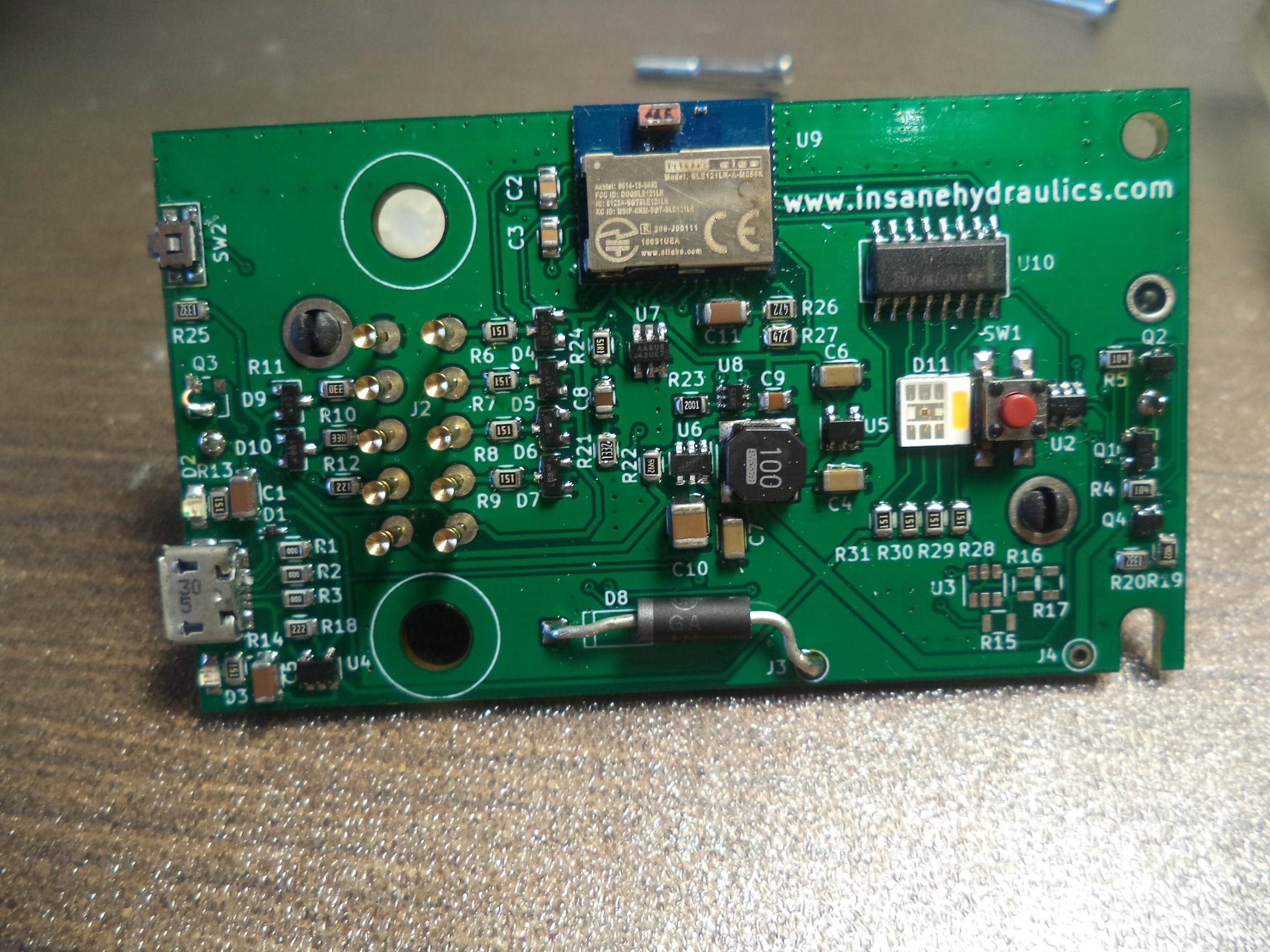
If you know your way about electronics - you will be able to tell that some of the design elements are indeed outdated. For example - I opted for controlling the RGBW LED with the ULN2003 driver (U10) - which is not the best of choices, to say the least. The IC has an enormous footprint, and aside from stealing a huge chunk of the real estate on the PCB it also steals four pins from the MCU! A better solution would be using a dedicated LED driver IC, which would also take care of controlling the LED current.
I used the MAX126054AZT (U2) for the on/off push button controller - and it is what it is - an electronic on/off button, not more not less. A rather expensive chip for what it does, I must say. There are better solutions now, a.k.a. smart button controllers, like, for example, the STM6600, which can single-handedly replace both the on/off controller and the battery monitoring IC (U3 - which I didn't even use), and also provide the option for enabling MCU-controlled turn-off logic, which could, for example, prevent you from switching off the device during a firmware update.
The charging IC that I used in this project was the MCP73831T (U4). This IC is a fully integrated Li-ion charger controller that has a max charging current of only 500 mA. On the one hand - this could be improved on, on the other hand - it is guaranteed to work from any USB port. In any case - it works and it is super cheap, but it does take a lot of time to charge the battery.
Now let us quickly inspect the sensor PCB.
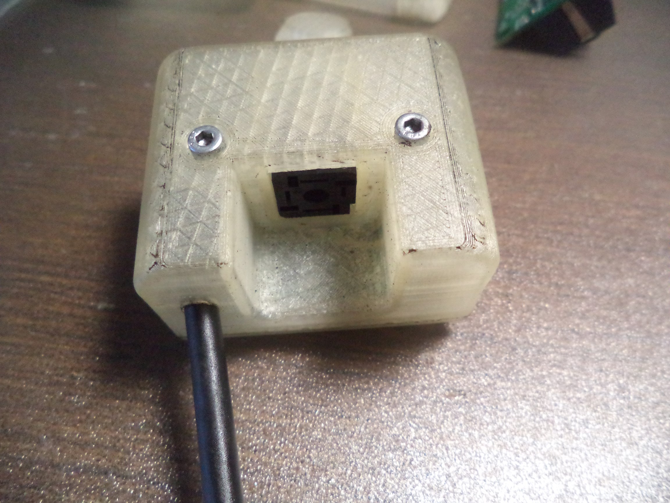

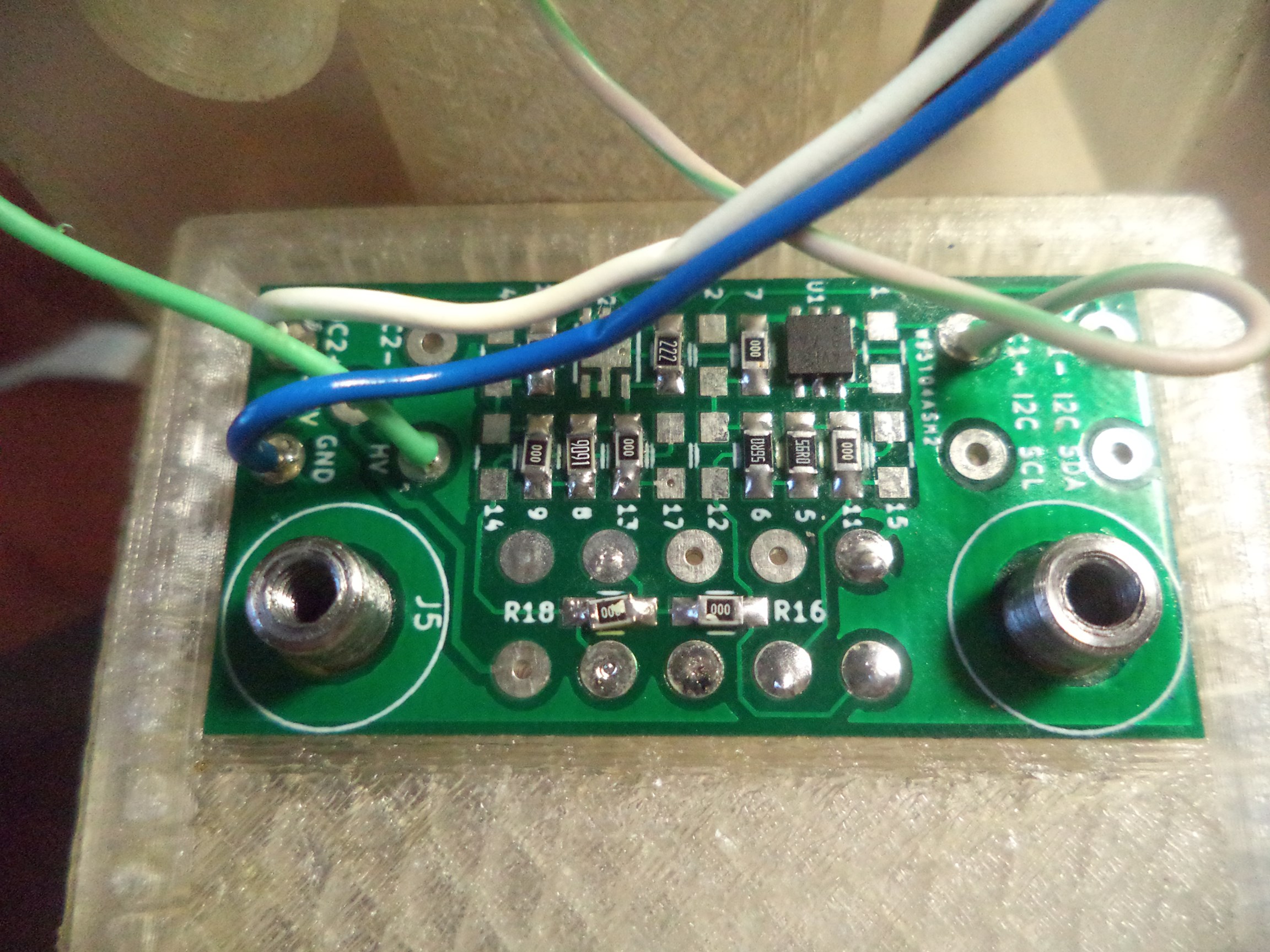
The PCB has extra footprints for either resistors or shunts - which allows me to use it with both current and voltage output sensors. I also used the MAX14626 loop protector - it is a great chip to have in a sensor circuit because it protects the loop sensors from over-current, short-circuit, and reverse input. This is especially important when you are connecting sensors "on the go" when situations like a wire touching another wire during a sensor hook-up can happen. This tiny chip (and it is indeed super small) takes care of it all - so don't be afraid of incorporating it into your design.
A few words about interfacing an industrial sensor with a microcontroller. There are a lot of solutions on the internet that involve some sort of a buffer or an operational amplifier - but in my experience - if your objective is 12 bits of resolution and you are using the ADC built into your microcontroller - all you need is a simple voltage divider for sensing voltage output sensors and a precision resistor for sensing current loop sensors. I've tested this countless times, and it simply works because the sensors usually have very capable output drivers built into them. You do need to use resistors with stable thermal characteristics.
So, as you can see - a wireless (Bluetooth) pressure gauge based on an industrial pressure sensor is an extremely simple device, and you can easily build one using readily available parts. I may even make a short video course one day on how to do it just to prove the point. Feel free to use whatever you may find useful (but please, copy only the good stuff).