Insane Hydraulics
Bold and audacious blog about fluid power


Today I want to talk about measuring pressure spikes in hydraulic systems and describe my own findings on how the length and the presence of air in common small diameter test hoses affect the ability to register pressure spikes in a hydraulic system.
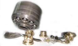
When you "hunt for spikes", you, obviously, use a "proper" digital pressure gauge, or maybe even an expensive data logger, but aside from your pressure measuring gear you also use a physical connection, which, in most cases, is a small diameter test hose that looks more or less like this.
If you take pressure readings on a regular basis, I'm sure that you carry a box full of these test hoses with you. I know I do. Of all sizes. And I have always wondered if the length of such a hose really mattered, and if it did - by what degree?
I'm sure that for static pressure measurement the length of the hose is not important, but what about dynamic pressure readings and especially fast pressure spikes? Shouldn't a small diameter test hose act a damper of sorts? I suspected it would, but I never knew for sure.
There's another thing that has always "bothered" me - the air inside the test hoses. I know technicians who never like storing away their test hoses with oil inside, and I can totally relate to that. When you store away a test hose filled with oil and don't cap it (or maybe the end caps are long gone...) - the oil will leak into your test-gear box, which is all but clean! Especially if the box is lined with rubber foam that will soak the oil in and become a not so pleasant thing to touch or even look at.
I have a friend who has a custom of using centrifugal force to clean his test hoses. Yep - you heard me right - the centrifugal force. He's a great guy and an extremely professional tech, and he is absolutely obsessed with keeping things organized - something that I, unfortunately, have never been good at.
His technique is genius (and I really mean it!) - after finishing a pressure measuring task he finds a "safe area", then takes the test hose and swings it around above his head like a medieval sling at an incredibly high speed to let the oil "spray out". What a sight, I tell you! The sound is beautiful too.
I have tried this exercise exactly one time - the test hose did get clean, but as I stopped rotating - the loose end of the two-meter hose wrapped around me and the 16x2 coupling lashed me in the face right above my right brow. This was not pleasant, I promise!
Anyhow - I was working on a Danfoss PVG32 project the other day, and a thought occurred to me - since the open center PVG32 is a perfect and consistent "apparatus" to create pressure spikes I may as well use it to test my "test hose" theory.
Wait... You didn't know that an open center PVG32 inlet module can create pressure spikes in the P line? Well - it can, and if your pump connection is a short rigid pipe - the spikes can be pretty nasty. I once had an unforgettable first-hand experience with this "peculiarity".
When the inlet section of such a directional control valve is configured as "open-center" (to work with a fixed displacement pump) the inlet module compensator closes the P to T connection when a function is activated, and when the working spool is re-centered relatively fast - the compensator spool takes some time to shift and re-open the T connection which creates the pressure spike in the P line. The severity of the spike depends on the P line elasticity and the flow rate.
By the way - the only thing you will find in the official Danfoss catalog regarding this phenomenon is the finely printed phrase - "In open-circuit systems with short P-hoses/tubes, attention should be paid to pressure peaks at flows >100 l/min [26.4 US gal/min]". So, yeah...
Let me get back to the spike test now, and describe the setup:
The "spike generating mechanism" consisted of an open center PVG32 that had a work section with a 130 l/min spool (I will describe this valve in detail in one of my next posts - it was used in a very interesting project, that definitely deserves special attention). The work spool was operated by hand. The pressure line was a two-meter 3/4' '4SH hose and I took readings at 30, 60, and 90 liters per minute, which resulted in relatively mild "spiking" - but hey, you work with what you've got, right?
To register the spikes I got a couple of "decent" digital pressure gauges, same model and range - namely the Parker SCJN-600s, which have the scanning rate of 10 msec (about 100 reading per second).
The basic idea of the test was: I would install one pressure gauge directly in the P line (the control gauge) and then use the other one with test hoses of three different lengths - the 1 meter, the 2,5 meter and the 5 meter one, operate the valve with 30, 60, and 90 l/min flow rate, and then compare the readings.
Then I would swap the gauges and repeat the test, just to make sure that tests are consistent and that I won't discover a difference between the gauges.
I would run the first batch of tests with the test hoses completely filled with oil, and a second batch with the hoses cleaned with compressed air prior to connecting them to the test point.
Here's the raw data from the tests. Since the two pressure gauges have the rubber boots of a different color, I am calling one of them "Red" and the other one "Black":
| Flow rate, l/min | Pressure Gauge | Control Red | Control Black | Control Red | Control Black | Control Red | Control Black | |
| Test Hose Length | 1 meter | 2,5 meter | 5 meter | |||||
| Test hose Filled | 30 | Red | 84,9 | 88,2 | 92,5 | 88,1 | 93,1 | 81,6 |
| Black | 84,4 | 87,4 | 88,3 | 86,7 | 76,4 | 87,9 | ||
| 60 | Red | 138,2 | 139,8 | 137 | 136,6 | 136,3 | 116,9 | |
| Black | 138,6 | 135,5 | 136 | 134,8 | 112,4 | 136,5 | ||
| 90 | Red | 156 | 152,4 | 156,6 | 152,6 | 158,1 | 126,5 | |
| Black | 153,8 | 152,6 | 156,8 | 152,6 | 128,3 | 156,4 | ||
| Test Hose With Air | 30 | Red | 85,9 | 89,2 | 85,5 | 80,7 | 89,8 | 28 |
| Black | 86,3 | 86,9 | 77,1 | 85,3 | 23,7 | 89,1 | ||
| 60 | Red | 131,4 | 139 | 135,9 | 133,2 | 135,2 | 86,1 | |
| Black | 131,9 | 139,8 | 131,3 | 135,8 | 80,6 | 136,3 | ||
| 90 | Red | 157,4 | 154,7 | 149,9 | 150,2 | 156,5 | 112,1 | |
| Black | 156,1 | 151,2 | 147 | 152,2 | 113 | 160,8 | ||
If you really want to study the data - you can download the open office spreadsheet with all the tables. Here's the "final" table where I averaged the readings:
| Inlet Section Flow Rate | Avg. Spike Magnitude, bar | Avg. Diff., 1,0m test hose | Avg. Diff., 2,5m test hose | Avg. Diff., 5,0m test hose | |
| Test hose Filled | 30 | 88 | -0,2 | 1,4 | 11,5 |
| 60 | 136 | -2,4 | -0,4 | 21,8 | |
| 90 | 155 | 1,2 | -0,1 | 29,9 | |
| Test Hose With Air | 30 | 88 | -1,4 | 6,5 | 63,6 |
| 60 | 136 | 0,2 | 3,6 | 52,4 | |
| 90 | 155 | -1,1 | 2,5 | 46,1 |
Allow me to resume these numbers for you:
As I expected - the longer hose resulted in a worse ability to register pressure spikes, but - to my surprise - even for the 2.5-meter test hose the difference was not significant. Even when it was filled with air! (at least for the spikes that I had "at my disposal")
I actually got so surprised that I thought that maybe my 2.5-meter test hose was kind of old and therefore lost its elasticity (one could definitely tell the difference between the old hose and a new one), so I got a brand new and seemingly very flexible hose from the warehouse and retested it - and I got the same results! Very interesting indeed.
Now the 5-meter hose was a complete disaster - no ability to register any spike at all. I found very curious the fact that when the hose was filled - it's "spike capturing ability" would become worse as the spike magnitude increased, but when the hose was filled with air, higher pressures resulted in lower pressure differential (still very unacceptable, and still much worse than when the hose was filled).
Conclusion - with relatively short test pressure hoses (up to 2 - 2,5 meters) you can safely measure whatever you like. But if you, for some reason, need a longer test hose - you can forget about dynamic readings.
I never use long test hoses simply because I use my wireless pressure gauges most of the time anyway.
Also - as you can see, an open center Danfoss PVG32 with a flexible hose P line and a flow-rate of about 100 liters per minute does create pressure spikes, but their magnitude is not alarming. However, if you are using such valve to assemble a power pack and run a short metal pipe between the gear pump and the valve inlet - I would encourage you to check for the presence of unacceptable pressure spikes, especially if the valve uses high flow spools and on/off controls. Such a system may require an additional fast-acting relief valve in the P line.