Insane Hydraulics
Bold and audacious blog about fluid power
This article describes technical causes behind the multi-section gear pump failure, described in Travelift Adventures, and also touches on a couple of gear-pump-related myths.
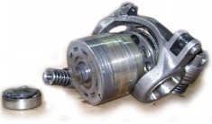
A five-section Parker gear pump, four sections of which were feeding independent Danfoss PVG32 proportional valves, spat out the housing seals after ten minutes of operation, causing notorious agitation of standers-by and appearance of grey hair on the head of the attending technician.

Before diving into the causes of this failure, I would like to talk a little about the pressure-induced forces that exist in "traditional" gear pumps, as well as to touch on a couple of gear-pump related misconceptions I come across fairly often. Let us start with a common sigle-section gear pump:

Here you have two endplates, one with a shaft sticking out of it and the other one blind, and a body with gears and whatnot in between. The "sandwich" is held together with bolts, which either are screwed into the threaded holes of the body, or pass through the sandwich and secure the parts either with nuts on the other end, or threaded holes in the endplate. Each of the plates has an area exposed to the outlet pressure which produces force directed to separate the plates from the body, and therefore creates tension in the screws. Let us pass on, now, to the myths, starting with
Not a myth, but rather a misconception I often see around "workshop population", and which concerns gear pumps that use pass-through bolts. With the threaded body and short bolts, the understanding of separating forces is straightforward and poses no difficulty - the internal pressure acts on the plate, creating a force that equals the exposed area times outlet pressure. If we had to calculate the tension stress in the bolts, it would be this force that we'd use in the calculation. However, in the case of passing bolts

it is often misunderstood that, as the upper plate creates an "area times pressure" force in one direction, and the lower plate creates an equal force in the opposite direction, the resulting screw tension force is doubled. This is wrong - the tension stress in passing fasteners is the same as with the threaded body design, and if we were to calculate the tension stress, we'd still use the same single area times pressure.
This misconception boils down to believing that in multi-section gear pumps, held together with long rods that pass through the whole assembly, the pressure-induced separating forces of every section add up, causing a much bigger tension stress in the bolts/rods than in the case of a single pump. Once again, let us look at the diagram:

The section with higher pressure creates a higher separating force, which is then transmitted to the screws through the endplate and the body of the section with lower pressure. The pressure inside this section does relieve the body from some of the stress due to the separating force acting on the endplates, but it doesn't add up! If we were to calculate the tension stress of the screws in a multi-section pump, we'd use the same single area times the highest pressure.
Now that we are clear about gear pump pressure-induced separating forces, let us go back to the malfunction and its
1) The first and most obvious cause, of course, is the quality of the threaded rods that were used to assemble the five bodies. But wait a minute... The shop that built the pump had used the same rods in single-section pumps for ages without a problem. So, what went wrong here?
Two mistakes were made during the rod choice: first - the rods were threaded through the whole length, and second - the grade was too low. The separating forces of a multi-section pump do equal to the ones of a single pump, however, since multi-section pumps use far longer rods, the same amount of tension force results in a higher increase in length, which is why the rods suitable for single section pumps can be not suitable for multi-section units.
And in any case, rods that are threaded through the whole length are a poor choice, because the thread reduces the effective load-bearing area of the rod, making it "thinner". For large multiple gear pumps the use of high-grade steel rods, which have threads only at the ends, is imperative.
2) The second cause of the rod lengthening was the presence of high-pressure spikes, and to trace their origin, we need to have a closer look at the operation of the PVG32 valve used in this system. Here's a section view of a PVG32 pump side module:

The relief function is accomplished by the compensator spool "6". When the pressure exceeds a set level, the small poppet in the valve "1" lifts from its seat, venting the left side of the compensator to the tank and causing it to dislocate to the left, thus connecting the inlet to the tank port. The relief function is there, but like in the case of any spool-type relief valve, it is relatively slow.
In that hydraulic system, each PVG valve had a section, controlled by an ON/OFF PVEO electrohydraulic actuator. These sections were used to operate the winch motors. Due to "let-us-get-rid-of-what-we've-had-for-years" reason, 100 liter per minute spools were chosen for the sections, which exceeded the pump supply, and so when the valve was in ON position, the compensator spool closed the P to T passage completely. When the solenoid was de-energized, the DCV spool would return to central position in about one-tenth of a second, which was faster than the pump module compensator could open the P to T passage, so whenever the ON/OFF solenoid was shut-off there was a pressure spike in the P line, caused by the combination of "slow" compensator spool and the fixed displacement gear pump unstoppable flow. By the way, the choice of a high flow spool can be gracefully explained by the desire to lower the spool pressure drop and therefore the consequent heating, as the winching function required no flow control and was to be operated for long periods.
There are several ways to address the problem. The obvious solution is installing pre-charged accumulators at the pumps' outlets. It is, probably, the best technical solution, but it is expensive and requires regular maintenance. A cheaper solution lies in installing additional fast-acting pressure relief valves to "clip" the spikes. One could also use a longer pressure hose which would damp the surges due to the hose accumulator effect. Another one is to limit the DCV spool travel (or apply a spool with a smaller flow rate) to the point where the compensator starts compensating. In this type of valve, flow regulation is done through metering the pressurized fluid to the tank, from P to T, so when the compensator meters flow, there is already a small passage open between the inlet gallery and the tank line, making the high-pressure surges unlikely. Yet another solution would be to find a way to dampen the DCV spool movement (by installing orifices in the pilot lines, for example), thus giving the compensator more time to open.
In that particular case, there were four fast-acting SUN relief valves readily available from the old installation, with all the fittings, pipes, and everything, so I opted for installing them directly at the pumps' outlets. Even when they were adjusted 40 bar above the PVG relief setting, they'd still spit out a jet of oil each time the PVE actuators were turned off. (I know this because I tested them with their exhaust ports unplugged. Ve-e-ery unsafe, kids, so don't do this at home!)
1) Multi-section gear pumps should be assembled with high-grade steel rods with thread only at the ends.
2) Danfoss PVG32 valves, as well as other proportional valves based on the same design, under certain conditions, can create high-pressure spikes in the inlet line. These include the combination of flow saturation condition (when the compensator spool closes the P to T passage completely, which can happen when a spool flow rate is higher than the pump flow, or when several spools are actuated at the same time, demanding more flow than the pump can deliver) and a fast release of the spool/spools to the neutral position (which is the case of the PVEO on/off solenoid).
3) Such pressure surges can be aggravated in fixed displacement pump circuits that use rigid (steel) piping.