Insane Hydraulics
Bold and audacious blog about fluid power


A long time ago a client of ours was talked into buying a Kawasaki K3V63DT pump. It was a standard excavator model with a Negative Flow Control (NFC) and since it had "lived" in stock for a very long time, it was sold at almost the cost price. Our client was (and still is) one of those firms who are lucky to have a team capable of designing and building their own hydraulic projects, so they were very happy to have acquired a tandem variable displacement piston unit with a built-in pilot solution for so cheap, and the plan was to use it in one of their in-house built crawlers.
A crawler is a self-propelled remotely controlled platform on tracks, used to transport heavy rigs in mines, and naturally, an excavator pump, i.e. a pump already used in thousands of track driven machines, seemed to be the perfect choice.
It was soon "discovered", however, that the pump control, advertised as "load-sensing capable" during the sale, had nothing to do with the classic closed-center load sensing systems the crew had been so accustomed to, and so the pump was put away "for a rainy day".
Several years passed, and then one day, when I was discussing the pump choice for an upcoming crawler build with their shop foreman (at that time we already had a very good professional relation) he showed me that pump and asked if I could find a way to make it work with a Danfoss PGV32. (Using the PVG would be extremely convenient because practically all of their equipment used this series).
"Challenge accepted!" - said I - "Hand me my thinking grenades, Carter!"
There were two paths to choose from. I could either find a closed center LS control module for this pump model or come up with a way to make the existing NFC work with a PVG32. My attempts to source an LS control for the K3V63 were unsuccessful, and so I decided to concentrate my efforts on finding a way to "marry" a Danfoss PVG32 to the Kawasaki's NFC. And, believe it or not, I found a very simple way to do it!
What is an NFC hydraulic system? If you look into how it functions "on the pump side" - you'll see that it is nothing but a simple hydraulic pilot proportional displacement control with a negative characteristic, meaning that increasing the pilot pressure decreases the pump's displacement.
Then, such a pump would be connected to a DCV, in which the central gallery is connected to the tank through a calibrated orifice, and the pressure induced by the restriction is fed to the pump control. When the spool is centered, the flow through the orifice causes the pilot pressure to rise and de-stroke the pump. And when the spool is shifted, the flow in the central gallery decreases, thus lowering the pilot pressure, and causing the NFC to increase the displacement. Here's a simplified schematic. The relief valve before the orifice protects the pilot line from pressure spikes, when the spool is centered and the flow through the gallery is too high. An elegant system, in my opinion.
So, I decided to transfer this arrangement to the PVG32. But how can you do this with a valve that doesn't even have the notion of the "central gallery" since all of the bypassing is done in the inlet module? The answer to this is - carry over! Yep - if you didn't know (back then this definitely was a revelation to me) - there is an option of a pump module for a PVG32 with a High-Pressure Carry Over (HPCO) function.
In theory, everything was supposed to work. I would connect my orifice and a relief valve to the HPCO outlet, and the fact that the inlet compensator would meter the amount of oil flowing to the HPCO gave me hope that I would not run into instability issues. It seemed like a perfect and easy solution, so I discussed it with the client - and we decided to give it a try.
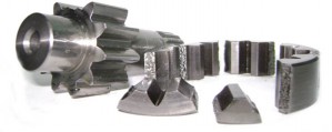
A few words about the main components (in case you want to go into details and look these parts up). The pump module was the 157B5140, which I coupled to a 157B6110 section and a 157B2500 endplate (there was a second auxiliary work section on each PVG, but it's not important for this story). Since it was a K3V63 that would run close to 2000 rpm, I chose the 157B7106 spools (130 l/min) for the travel function. Then, for the orifice, I used a simple 1/4'' needle valve, which I coupled to a direct-acting relief valve. Check out this picture - the gorgeous K3V with the two PVGs in the front. What a beauty!
So - we put it all together, and gave it a go - and you know what? It worked! It freaking worked right out of the box! Or at least I thought so... I quickly set the pressures, found a reasonable setting for the orifice, and the pilot relief valves - and since everything seemed to be working fine, we decided to take the crawler "for a spin". It was then when I saw a very strange problem. One of the tracks was running slower than the other. Not by much, but enough to force the operator to be constantly "compensating", which was workable but not ideal and clearly required rectification.
As it is always the case with mining related builds, we were on a very tight schedule. I did manage to swap the pumps and saw that the problem "stayed" on the same side, and I also confirmed that the pilot pressure on the "bad" side was slightly higher - in fact, it appeared that even when the 130 liter per minute spool was shifted completely, the inlet module was still bypassing some oil into the HPCO, causing the pilot pressure to swivel the pump down, which seemed almost impossible, given the fact the PVG was brand new and the pump was only supplying about 110 l/minute. But the pilot pressure was there... Plus - why would there be a difference between the two brand new factory-supplied valves with exactly the same specs?
It was clear that further investigation was needed, but unfortunately, the client could not wait and made the executive decision to send the crawler to the worksite "as it was". Well, catch you next time, Mr. Crawler!
So, the machine worked for several years. Never failing, but always with one track slower than the other, and finally, a couple of months ago, it "returned home" for a major overhaul, which meant that I finally had my chance to once again lay my hands on my makeshift NFC system.
I dismounted the two PVGs and before making any changes ran them on the test bench. I connected the P of the inlet module to the pressure outlet of the bench, a pressure inducing valve to the work ports (to simulate load), and I installed on oval gear flow meter in the HPCO port to be able to monitor the by-pass flow with precision.
A separate word should be said about these flowmeters. Such an under-appreciated tool they are! The model that I use most of the time is not built for hydraulics, but rather for metering diesel or lubrication oils. It can't take pressures higher than 20 something bar, and stops working when the oil temperature is above 75 C, but - it is invaluable when you need to measure very low flows (like when you are "hunting for leaks") and yet it is still capable to take on flows up to 100 l/min. Since it has two displays - the total volume of fluid, and the instant flow in l/min - it is good for both tiny and reasonable flows. You can't do this with a turbine meter, and it is much safer than the good old bucked plus stop-watch technique.
Anyhow, I tested one valve, then the other. My test bench can output the top flow of 96 l/min, and I was really surprised to see that with the full flow of 96 l/min going into the P of the inlet module, and the 130l/min spools completely shifted, the "bad" valve was by-passing about 10-11 l/min into the HPCO port, and even the "good" valve was showing the by-pass flow of about 3-4 l/min. How can this be possible with 130 l/min spools? Shouldn't the inlet compensator be completely closed? 96 liters is way below the stated 130.
It was clear that the inlet module compensators were bypassing, but I wanted to find out why. So I decided to measure baseline values:
Baseline value Nº1 - compensator delta-P. I installed a pressure gauge in the P port and another pressure gauge in the work-port, shifted the spool completely, fed a flow of 20 l/min into the P, and then slowly pulled the spool back to neutral and noted the pressure differential when the HPCO flow meter started to register flow. The valves registered approximately 7,5 and 8 bar.
Baseline value Nº2 - own delta-P. I fed the flow of 60 l/minute into the P port, shifted the spool to the end of travel (compensator completely closed, i.e. zero flow in the HPCO), and registered the delta P. On both valves it was about 4,2 bar.
OK now, so two things were happening here. First - there was a small difference in the compensator biases, and second - the own pressure drop (caused by the resistance of the internal oil passages, the work module's check valve, and the spool notches), even with the spool completely open was getting too close to the compensator's pressure. And what I wanted was to
a) equalize the compensator deltas on both inlet modules, and
b) make sure that with the spool completely shifted there would be no HPCO flow.
In order to achieve that I would need to increase the "compensator delta-P" or decrease the "own delta-P". I decided to do both.
First - I removed the check valves from the work sections. In this application, the check valve was not necessary because each of the track motors had a motion control valve. Removing the check valve resulted in the 60 l/min pressure drop going from 4,2 down to 1,4 bar. Great improvement!
Then I disassembled the inlet modules (there was indeed a small difference in the bias spring height), found a couple of similar (but equal) bias springs from scrapped modules and added a second spring (not sure where this one came from, but I had two of them and after a small lathe job they fit perfectly in the middle). The pressure drop (tested, as before, at 20 l/min) increased from 8 bar to 9 bar. Another step in the right direction!
After these changes both of the PVGs were no longer by-passing on my test bench (with its maximum flow of 96 l/min and the spools at the end of travel).
So, we re-installed the valves on the crawler and immediately saw a clear difference! Fist of all - it became a tiny bit faster. And then, the best part was that now it was going straight! Well, almost straight, because there was no straight travel valve, but still - significantly better than before.
So now I can say with certainty and with a clear consciousness that you can make a PVG32 work in an NFC system with a K3V pump!
Unfortunately, as always - I didn't get more time to work on the crawler. I would love to log the flows, pilot pressures, overall system's efficiency to see how it would compare to a classic closed center LS system...etc... but still - It works! And I learned something new!
To resume - proportional DCVs (like the PVG32) when configured as open center (and in our particular case the HPCO port would be equal to the tank port of the standard open-center PVG) work with the delta-P of the inlet module compensator, as opposed to the closed center configuration, when they work with the delta P set at the pump's LS spool. This means that a spool rated at 130 l/min in a closed center LS configuration, can be incapable of supplying its rated flow in an open center configuration due to the fact that the inlet module compensator bias spring has a lower delta P. In other words - a 130-liter spool is not always a 130-liter spool! Be very aware of that!
Additional notes (approximate adjustment values for those who want even more detail):
The pumps had the minimum displacement locked at about 18-20 cc (flow of 35l/min at 1900ish rpm). I wasn't able to change that, by the way. The adjustment screws got so stuck that I could not turn them.
The NFC was starting at 25 bar and gave full displacement at approximately 8 bar.
The makeshift orifice was set at one full turn from closed, and the pilot relief was set at 27 bar (at the working temperature of 50 C and 1900 rpm or 35 l/min in the HPCO). It was interesting to note that the relief valve itself acted as a decent orifice because of its relatively high pressure override).