Insane Hydraulics
Bold and audacious blog about fluid power
A real life episode this time, and a sad one...
A recently overhauled open circuit hydraulic pump - a Rexroth A10VO45DFLR - equipped with the pressure compensator, load sensing, and torque limiter regulators, was being tested on a bench in an "undisclosed" hydraulic shop. The client had requested the torque limiter to be set to 15 kW (20 hp) at 1450 rpm, which was the nominal power/speed of the electric motor driving the pump. The request was made due to the plant electrician's advice to limit the motor current consumption to 30 amperes. In fact, the exact words were - "adjust the pump to 15 kW or 30 amps".
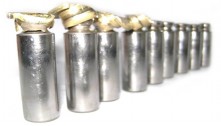
The test bench was very basic - a common AC induction motor, an oil tank, a needle valve, and a flow-meter - a simple, yet functional combination. The technician that was testing the pump even went to the trouble of finding a typical AC motor current table, like this one:

which confirmed that the current draw of a 15 kW motor (three-phase, 380 volts, 50hz) rounded 30 amps. And then, to adjust the torque limiter, he proceeded exactly the way he had adjusted many similar controls on pumps driven by electric motors before - by reading the phase current and setting the regulator so that the current doesn't go over a certain value.
The "adjusting maneuver" was performed "by the book" - the current draw in one of the phases of the test rig motor was being monitored with a quality current clamp, the torque limiter was set to start cutting the displacement at 30 amps, and then to maintain the current roughly at 30 amps until the pressure compensator kicked in. However, when the actual hydraulic output (pressure times flow) power was calculated, it turned out to be in the neighborhood of only 7kw (10 hp)!..
After more tests, a conclusion was made that the pump's overall efficiency was unacceptably low (50 percent). As the pump didn't have excessive case leakage, the fault was attributed to low quality spares causing "excessive mechanical drag" and the unit was rendered "faulty beyond repair". Furthermore it was decided that the pump needed to be replaced with a new "original" one, and the client once again had to face expensive downtime costs until the new pump arrived.
What is wrong with this picture?
If I were asked this question, I'd say that before answering it I'd need to know how big the test bench electric motor is. Why? Because of this little thing called "power factor", which is a strictly AC-related term, and in simple terms is the ratio of the active power to the apparent power, with the apparent power being the product of measured current and voltage, and the active power being the portion of the apparent power that your motor is actually consuming to perform work.
Most industrial three-phase motors have a power factor of around 0.85 at nominal loads, and the above-mentioned table is only valid for nominal load values. When a load of an AC motor is less than nominal, the power factor (along with the efficiency) drops:
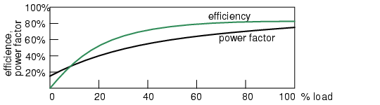
This means that the phase current of a lightly loaded motor can not be used as a reference to determine the output torque simply because it indicates mostly the apparent power and not the real one.
Due to the fact that the test bench in question was built to be able to test larger pumps (the AC motor of the rig was rated to 70 HP), the motor load was well below its nominal value during the test of the "malfunctioning" pump, and therefore the phase current the mechanic was reading didn't represent the real load current.
In this case not knowing what an AC motor power factor is caused extensive downtime and unnecessary expenses. This example shows that knowing a thing or two about what is at "the other end of the shaft" can't hurt a pump mechanic. Understanding at least the basic theory of industrial motor and engine operation has become an essential part of a "knowledge package" any hydraulic technician should carry under his belt.