Insane Hydraulics
Bold and audacious blog about fluid power


My discussion of closed-loop charge-pressure-related stuff (which I began in part1 and continued in part2) would be incomplete without addressing the loop flushing subject, which is, therefore, the prime topic of this post.
The main purpose of a closed-loop flushing system is to renew the oil inside the loop during transmission operation, thus making sure that it runs cool and clean. Is it mandatory? Well, not at all. You don't need a flushing system for a closed loop to function. But you do need it for it to last. There are, of course, tiny closed loop transmissions that can operate without any loop flushing, but this is only viable for very small sizes or very intermittent duty cycles.
Any loop flushing system can be divided into two parts - the directional part, which serves to always pick the low-pressure side of the loop to work with, and the purging part, which serves to divert oil from the loop. In most vehicle propulsion closed loops the flushing system is incorporated into the drive motor. In industrial applications, however, it is not uncommon to find external loop flushing manifolds.
The classic layout of the directional part consists of a dumbbell-shaped spool (cut-view), which functions in the following manner. It is possible to come up with a different spool design - like, for example, two separate poppets that touch each other instead of a single spool, but the final purpose is always the same - choosing the low side of the loop to purge. In some cases, system designers adopt the use of solenoid operated directional valve/valves instead of the shuttle spool and in this case, the loop flushing is controlled electrically. And in some motors, the complete flushing solution can be integrated into a special valve plate.
The purging part of the loop flushing arrangement is the part that should interest us the most, because it is directly connected to the charging system, and therefore can influence the charge pressure. Let us take a look at different ways the purging can be performed:
1) Classic purging, done utilizing a relief valve. In this arrangement, it is very important to adjust the purging relief valve below the setting of the pump's charge pressure relief valve (usually 3 - 5 bar lower), as well as to understand that it is this valve that defines the charge pressure level during transmission operation. In such a system, the flushing flow equals the charge pump flow minus the leakage, and it is very easy to confirm its correct operation by monitoring the charge pressure drop when the pump is on stroke.
2) Relief + orifice purging, done by means of a relief valve combined with an orifice. A relief valve is set to a relatively low threshold, and the purge flow is then determined by the orifice size. Most of the times the spring setting is fixed. Some designs will allow you to exchange orifices. Depending on the size of the orifice, the charge pressure may or may not drop during the operation. The best way to confirm its correct operation is through measuring flushing flow (i.e. motor case flow) - an important verification - because, like any orifice, this one can get blocked and cause a malfunction of the flushing system. In such a system, the flushing flow is a percentage of the charge pump flow and is defined by the orifice size and the charge pressure setting.
3) Simple orifice as a purge valve - by far the most compact and simple solution you could imagine. Its main drawback is the fact that it doesn't have an opening threshold like the system described above (defining minimum charge pressure level), which can become an issue during low speed (and, consecutively, low charge flow) operation, causing the charge pressure to drop below the acceptable level. The integrated flushing valve built into a motor valve plate is one example of such a system - there's no place for a relief valve inside the valve plate, therefore the purge flow limitation is done by restriction.
4) Flow limiter as a purge valve - a solution that is rarely used in closed loops (no need to go that complicated) but can be occasionally be found in open-loop transmissions. When such a purge valve is used in a closed-loop, there also will be no noticeable charge pressure drop during the operation.
As you can see, it is the type of flushing system that defines if and how much the charge pressure drops when the pump is on stroke, and consequently, it may or may not influence the charge pressure setting. For that reason, it is important to identify which type of flushing system is used in a closed-loop transmission before adjusting the charge pressure.
Flushing solutions offered by different brands have their design and performance peculiarities, which is why the most perfect "loop flushing learning material" is technical catalogs, which will provide you all the data you may need.
I am concluding this article with these files, which are a good place to start if you want more detail about how "the big boys do it".
Sauer Danfoss Flushing Manifold.
P.S.
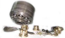
Another important loop flushing issue to consider is the fact that, like any high pressure exposed component, the directional part of a loop flushing system (the shuttle spool) can become the point of high-pressure leakage and cause the transmission to malfunction if damaged or worn out, which is why it is important to check it for excessive play every time you overhaul a motor equipped with one. You can see a good example of such wear is in this short video, which shows a loop flushing block from an ancient Sauer Danfoss series 20 motor.