Insane Hydraulics
Bold and audacious blog about fluid power


In my previous post I discussed how high the charge pressure setting of a closed-loop should be, and today I want to continue with the topic and talk about the peculiarities of measuring charge pressure in hydrostatic transmissions.
Despite the charging circuit of a typical closed-loop being relatively simple, there's more than one way, or better - place - to take the charge pressure reading. Whether you are simply adjusting your transmission or troubleshooting a malfunction - it is important to understand the difference between these measuring points, and know how to interpret the readings.
Let us take a look at a typical closed-loop charging setup (the pressure gauges in the diagram indicate the places where you can take readings):
Here we have the charge pump, the charge pressure relief valve, oil conditioning components (the filter and the optional cooler) and the check-valve. Even though it is not relevant for this context - I still put a suction filter in the schematic, as well as the suction line pressure measuring point - just to demonstrate that this option exists and can be used to verify the suction line condition.
Note that I also included not one but two relief valves in the schematic. The actual position of the relief valve in a charging circuit (whether it is placed before or after the oil conditioning components) will depend on the manufacturer. Some pump brands can even have both - one being a safety vale (the one installed before the filter or cooler to protect them during cold starts, usually set around 5-10 bar above the "normal" relief valve setting), and the other one being the charge pressure relief valve.
As you can see - there are three points where we could install our pressure gauge and take a reading:
Let us consider these options one at a time:
This is a valid place to read charge pressure for "adjusting" purposes, and often there will be a conveniently placed test fitting, but there's a catch - in pumps that have charge pressure relief valves installed before the filter - clogging of the filter will result in insufficient oil supply to the loop and the consequent cavitation, without a drop in the charge pressure reading. Sauer Danfoss series 90 is a good example of such pump design. (I keep calling these pumps Sauer Danfoss, for some reason, even though they are plain Danfoss now...)
This is a better place to measure charge pressure, because now, obviously, you won't be lead into error in case of clogging of the oil conditioning components, and most of the systems have a test fitting in this point as well. However, in case of the check valve malfunction, the loop will still cavitate without a drop in the charge pressure reading, once again making it possible to come to an incorrect conclusion.
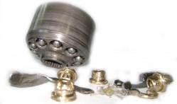
Despite what some might think, it is possible for such a simple and "bulletproof" thing as a check valve to malfunction. For example, the Sauer Danfoss series 90 multi-function valves can easily fail due to particle contamination. In some small-sized closed-loop pumps, the check valves are small ball valves, that can damage the housing with time and fall into the oil passage blocking the loop feeding gallery (example). Want another example? - Take a look at these two check valve/relief valve assemblies from Rexroth A4VGs of different sizes. As you can see - the threads are equal, while the travel of the poppets is not. If the smaller pump by mistake gets the "bigger pump valve", the poppet will have very little travel, resulting in partial blockage of the charge oil passage and the consequent loop cavitation.
It must also be noted that the charge pressure in this measuring point will be affected by the oil conditioning system pressure drop (will be lower than in the point 1) - something that can be used for filter condition monitoring, for example, or for verifying if the cooler is obstructed.
This is the best place to see if the loop is cavitating because any volumetric or charge problem will be immediately indicated by a pressure drop. One thing you don't want to do is to use a low range pressure gauge in this place (unless, of course, you are fond of collecting busted pressure gauges). While in the two cases described above you could safely do that, a high-pressure spike can happen in the low-pressure side even when the pump is controlled in the right direction, so if you use a 60 bar analog gauge - it will be the last time you use it. I suggest a decent digital pressure gauge or an analog one with a large range (250 bar +) - although it will be difficult to precisely read low-pressure values on a high-range scale, you should at least be able to see if the charge pressure is dropping or not when the system pressure rise.
Note that when you read charge pressure directly in the loop, especially on old equipment, you must be ready for pressure fluctuations due to drifting null (articles on null adjustment here).
To resume all of the above:
If you are simply adjusting the charge pressure of a functional closed-loop transmission, the most convenient points to read it are points one and two. Even better - both at the same time, because comparing the pressures will give you an idea of the pressure drop caused by the oil conditioning components, and thus will help you decide whether the filter/radiator needs to be changed/cleaned. In this case, it is OK to use low range pressure gauges.
If you are troubleshooting a malfunctioning closed loop and are suspecting that it has volumetric problems - you should grab a digital gauge or a high range analog one and measure pressure in the low-pressure side during operation, and then, if the cavitation condition (charge pressure drop) is confirmed, you should measure the charge pressure at point one, to see if it drops too. If it's not dropping, the malfunction is most likely being caused by the charge oil flow interruption either due to the filter/cooler clogging or due to a check valve malfunction.
Of course, there's also a possibility of the compromised suction line, which can be confirmed by measuring vacuum in the point zero, but since this article is about reading charge pressure, I am leaving this part out.
Understanding the difference between various places in a closed-loop transmission where you can take the charge pressure reading is very important for correct charge pressure adjustment and efficient closed-loop troubleshooting.