Insane Hydraulics
Bold and audacious blog about fluid power

I've been turning down random requests for technical assistance because we are totally (and hopelessly) booked for at least a decade, but on this occasion, I had to "drop everything" and go check it out because the technician troubleshooting that Komatsu PC88MR-6 excavator was very experienced, and when an experienced tech asks for my help because a pump is acting out - I need to see it! Plus - it was a ten-minute drive from our shop, which is a luxury one doesn't get every day.
So, the hydraulic system of the excavator was stalling the engine when a cylinder would hit the end of travel, even with the engine revved up. This failure can be caused by a number of things - and today I'll be talking about the diagnostics - i.e. how we came to the conclusion that it was indeed the pump that was causing all the havoc, and next week we'll crack the pump open and peek inside (Hurray! Back-Engineering!) This pump (LPD 45 + 45) is an engineering gem filled with hidden traps and genius/weird design choices - so it's going to be fun, I promise!
Let me start with some theory. Virtually all excavator pumps, independently from the type of displacement control (be it negative flow, positive flow or load sensing), are equipped with a torque limiting control (a.k.a horsepower control, but in my opinion the "torque limiter" is a more accurate term, because the pump does not "know" at what rpm the shaft is turning, it only tracks the displacement and one or multiple pressures - hence - torque), and virtually all of these controls have a means of overriding its setting because the diesel engine needs "additional attention" at low/idle rpm. Usually, the torque limiter setting override (often referred to as the "power shift") is done with the help of an electric proportional reducing valve, which injects controlled pilot pressure behind a piston that "helps" the main torque-limiting spool shift the pressure-times-flow curve along the pressure axis (you can visualize the PxQ curve and how the overriding pressure affects it in this interactive graph).
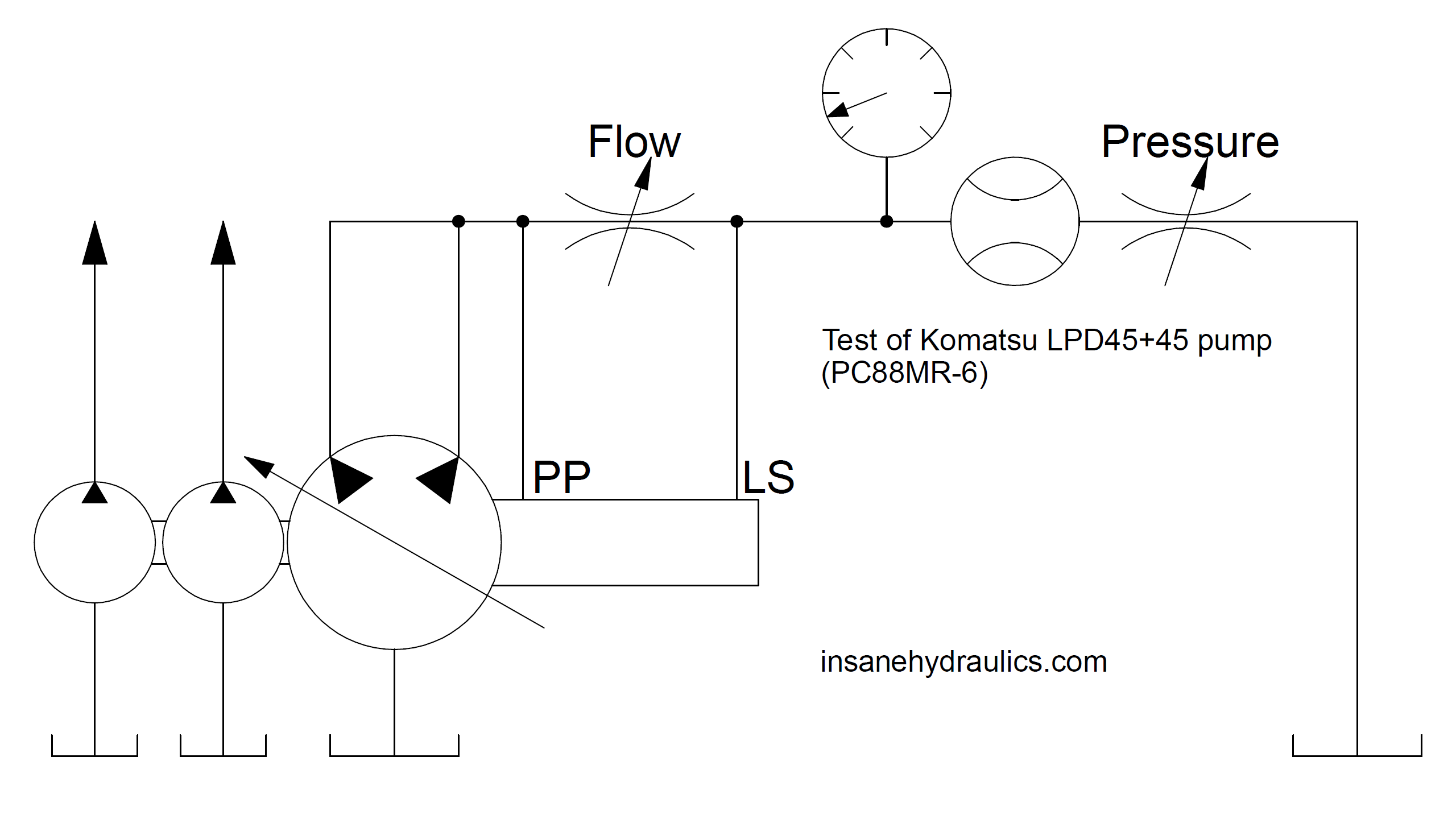
Excavators have relatively complicated hydraulic systems - but the "worst" is always on the "excavator side", the pumps themselves are simple - the rotary group/groups, the displacement controller, the torque limiter, and... that's about it! The PC88 pump is a classic in that sense - it has the load sensing displacement control, the mandatory torque limiter, and a torque overriding proportional valve that sits right on the side of the control manifold - so - it's all there - all you need to know is what to measure, where to measure it, and what readings to expect. I would say the only way Komatsu's LS control differs from a classic industrial LS is that the upstream part of the delta-P is fed to the LS spool from an external line (as opposed to a direct internal connection to the pump outlet).
So, let us think about it for a minute - how would one "sabotage" such a pump into over-consuming torque? I bet most of you are already thinking about an electrical problem with the power shift valve, aren't you? And you are right - any troubleshooting should start with checking the easiest things first, and reading current with a (girly) multi-meter is a lot easier than, say, inserting a (manly) flow meter into a high-pressure line to get a flow rate reading. This is tongue-in-cheek, of course, because despite the fact that the cordial rivalry between the mechanical and the electrical will never end, I would never suggest that electricians with their couple of pounds worth of pliers in a pouch (or a waist apron) somehow have it easier than industrial mechanics swinging spanners the size of a human arm from a toolbox that can only be lifted by two adult males...
But I got sidetracked - let us get back to checking the solenoid valve. Modern excavators are smart enough to detect things like disconnected connectors or burnt coils and show it on the display as soon as you turn the ignition key, but sometimes these electronic controllers do fail, which is why almost all excavators have an emergency switch hidden somewhere in the cabin which can power the power shift coil with a permanent current allowing you to safely finish operation should the electronics "go bad" - so it's a good place to start. The tech diagnosing the digger knew this well - so he did try the emergency switch - and it didn't work. Then he checked if the coil was receiving the correct current - and it was - between 400 and 900 mA.
So, the easy part was done by then, and it was time for wet tests. He then checked if the pilot pressure coming from the power shift valve was correct and was following the current (the pump has a pressure port for this - all of these details will be duly described in next week's back-engineering session) - and the valve behaved correctly - about 30 bar at idle (900 mA) and about 7 bar ar full rpm (400 mA).
Then he tried changing the mechanical setting of the torque limiter - and saw no response, and then he tried changing the setting of the LS valve and, quite surprisingly, once again saw no response. He then removed the control valve from the pump and carefully disassembled and inspected it - and found no stuck spools or clogged orifices.
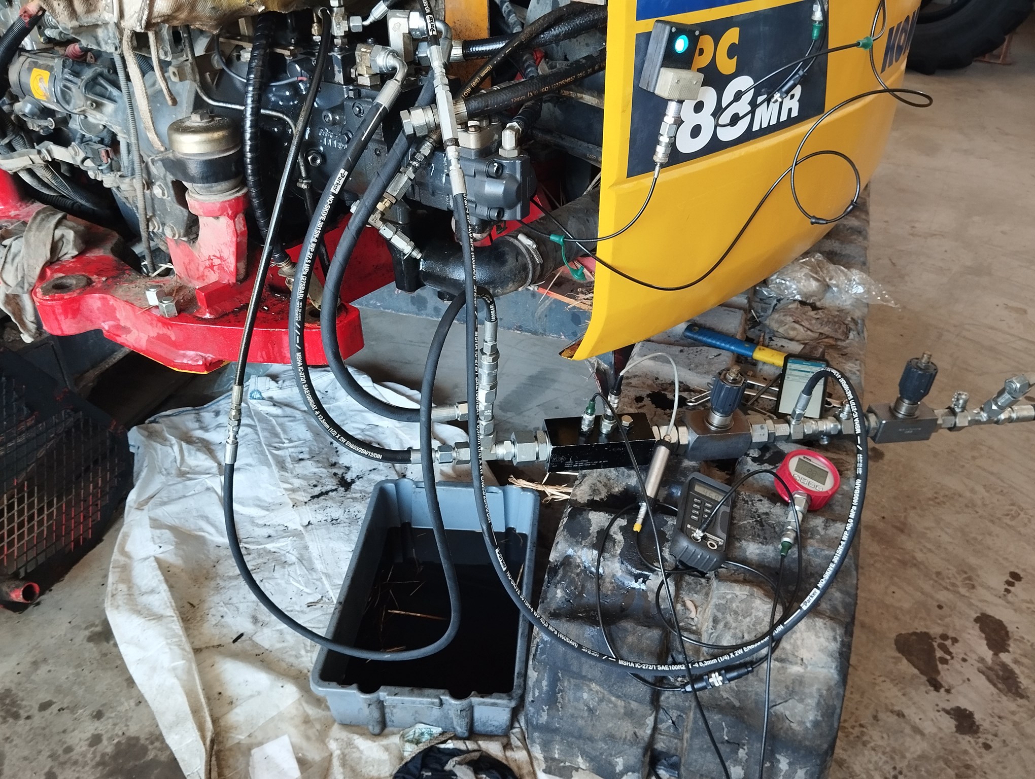
That was my cue to enter the scene. I didn't need to check much because I knew the man well enough to know that if he said he checked it - he did, and it was exactly as he described. I did, however, connect my wireless pressure gauges to the LS line and the PP line (both legs of the delta-P "scales") to check the delta-P when cylinders were moving. I always like to confirm the delta-P when "flow is happening" - in other words - when a pump is at mid-displacement because often a positive minimal displacement setting or construction of a servo-piston (among other things) can make a stand-by pressure unusable for verifying the real delta-P setting of an LS pump control. Here you can see the first pressure sensor connected to the PP (pump pressure), the second sensor connected to the LS, and my smartphone lying on the cabin floor and (very conveniently) showing me the pressures in the two lines, and the real-time delta-P between the two readings - this is way easier than looking at two pressure gauges at the same time and attempting mental calculations on fast-changing readings. Wa-a-a-y easier!


By the way, if you wonder why the readings show 35.3 bar and 4.1 bar and the delta-P is presented as 31.1 bar (in other words - 0.1 bar "is missing") - that is so because the math window makes a calculation when the primary reading it is attached to changes, and since the readings are received asynchronously (at a rate of about 7 readings per second), the reading of the second channel can update while the master reading hasn't updated yet - hence a small (0.15 second) lag in the math output is possible.
I did confirm that changing the LS setting of the pump control wasn't affecting the delta-P at all! It always oscillated between 25-30 bar when arm movements were made.
When I see a pump that does not respond to an LS setting change, and I don't find any plugged orifices or stuck spools - I begin suspecting internal servo-mechanism issues. So - the next thing I did was measure the pressure of the de-stroking servo cylinder - an ideal place to see exactly what is going on in a pump, and luckily this Komatsu pump has a diagnostic port for that! I also did the good old displacement limiter trick to see where the swash-plate of the pump was and... to my surprise - it was not a minimal displacement, but it was at maximum displacement!
As soon as I loosened the max. displacement limiter screw and turned it in - I could clearly feel how it touched the swash plate, and I could actually see the stand-by pressure going down as I was turning the screw in (reducing the flow). Full displacement is not a good stand-by condition for an LS pump, is it? Now, if you are used to classic industrial load sensing systems - you may find it strange that the pump is stuck at full displacement and yet I don't see it "scream and fight" against the closed center of the DCV - but the DCV of this system is actually not closed-center, but rather carries two 29-bar unloading spools in the inlet module (one for each pump) - just like a normal open-center proportional DCV would - this allows this system to operate with the min. displacement set above zero for fine-controlled movements.
When I checked the servo-pressure - I saw that it was way lower than it was supposed to be - about 30% of the pump outlet pressure, and with the LS spool totally shifted I was supposed to get a reading very close to the pump outlet pressure! So - there was, apparently, a major leak in the servo-cylinder, and when we removed the control valve and blew compressed air into the servo-cylinder hole - we could hear the air hissing out inside the pump. Not a good sign at all! To make things worse, the control feeds the servo-cylinder via an orifice, and this means that even a relatively small leak can affect its function.

At that point, the owner of the excavator wanted to see if there was a way of finding a temporary fix, and I suggested that we remove the orifice to increase the control's servo-flow capacity and see if maybe this could temporarily resolve the issue and allow him to at least move the machine to a better spot, but I also advised that there was as serious risk of the pump failing catastrophically in our hands because we didn't know how bad it was. A decision was made to give this a try - and we removed the said orifice, and then I disconnected the pump from the system and ran it through to my flow meter:
But even with the orifice removed, the leak was so bad that servo pressure wouldn't rise and the swash-plate would not swivel back - and so we removed the pump from the excavator and brought it back to the shop.
And... (drum roll) here are the culprits: one of the two servo-cylinders got completely stuck in the (very scored) bore, and the other one had the spherical joint of the shoe worn out so badly that it gained a play of almost a centimeter(!), and this is exactly where the leak was happening. Check out how deep the shoe falls into the piston! I've never seen a ball joint wear like that before!


So yes, the servo cylinders are busted, but we'll get the parts and have the pump running in no time. No problem at all. There is, however, so much more to this pump than meets the eye, and I will take full advantage of it ending up on my "operating table" and will be revealing all the details of this unit in next week's post. Stay tuned!