Insane Hydraulics
Bold and audacious blog about fluid power
The following episode is from my early "troubleshooting" years - the times I thought I knew it all...
That time I went to "investigate" a warranty claim for a recently overhauled closed-loop transmission of an aircraft tug that was operating at a remote airport in the South. The transmission consisted of a Rexroth A4VG56 pump, equipped with automotive control, and two A6VM motors - one for each axis.
The pump and the two motors had entered our shop with the usual "not enough force" complaint. Since no significant damage was found the overhaul was minor - the rotary groups were lapped, the units got new seals, and after passing the bench tests sent out to the customer. However when the machine was put back in service, the "not enough force syndrome" continued. I knew the mechanics who recommissioned the machine, so I was sure it was not the case of an "unhealthy" start-up procedure. It was obvious I had to go there and see the tug in action for myself.
A few words about these machines. Despite being small, these plane pushers/pullers are very heavy. Their frame is made of thick steel sheets to give them the extra weight needed to provide the necessary tire traction to be able to "push around" large airplanes.
The problem was an apparent loss of torque in the forward direction when the oil "got hot". As the mechanics had lots of machines with hydrostatic drives "in their care", they knew well that when such transmissions became "weaker when hot", they would need an overhaul - the main reason why they'd sent the complete transmission to our shop in the first place. Only this time the overhaul didn't work. The machine seemed to operate fine with cold oil, though, and the reverse seemed to work OK as well.
The "lack of force" was being tested on a short ramp the machine had to crawl up to enter the airfield. Even though the inclination of the ramp was rather modest, the heavy tug could only climb it when the hydraulic oil was cold.
Nobody could tell me what the normal operating temperature for this machine was since as usual there was neither a temperature gauge nor a history of temperature readings. So we took the machine for a spin, and I saw that the loss of torque was starting to happen when the oil temperature hit 80 C. The equilibrium temperature was around 85 C (with an ambient temperature of about 25 C). A bit too high to my liking, but it's not uncommon to find mobile equipment around here with these levels, and the Portuguese hot climate is one of the reasons for it. The tug was quite old, and I was told that it had already clocked several thousand hours of problem-free service with the same type of oil, VG 46, high Viscosity Index, and the same temperature. Go figure! If the pusher was mine, I'd install an additional radiator to lower the oil temperature to at least 70 C.
Anyhow, the lack of torque was there and needed looking into. The first thing you want to measure when troubleshooting a closed-loop transmission is, of course, the charge pressure. Frankly speaking, I was sure I was going to see it plunge, but that was not the case - the charge was dead stable. OK then, next thing - the high pressure. Aha! It appeared, that the loss of traction force was being caused by insufficient high pressure, which did not pass 350 bar with hot oil, which was not enough to climb the ramp. But what was causing it?
Suspecting control issues, I installed a metric thread measuring fitting into the forward servo cylinder, took the pressure reading, then did the same thing to the reverse side. The control pressure coming from the DA (automotive) valve, with the motor accelerating at 2200 rpm, was around 25 bar for both sides, which was supposed to be more than enough to maintain the maximum pressure of 420 bar. The reason I was measuring one side at a time was very simple - I only had one fitting with the metric thread in my toolbox at the time. Apparently, the servo pressure was not the problem...
Suspecting a relief valve malfunction, I dismounted both of the valves, inspected them, and didn't find anything wrong. I then switched the valves to see if the problem changed sides. Nothing changed...
One of the motors used in the transmission was of a variable displacement type, so it also "fell under suspicion", however (luckily) it was very easy to swap the loop lines at the pump side, which was the next thing I did. Swapping the hoses inverted the problem, so it was definitely the pump. Since there was not much else I could do, I dismounted it from the machine and brought it back to the shop.
Opening the pump revealed no signs of damage to the rotary group, which proved that the start-up had been done properly, so the pump was reassembled and now all I needed to do was invent a way of simulating the malfunction on our test bench. I already knew for a fact that at the normal bench oil temperature of 50C the pump was operating OK, so "to heat things up" I connected the charge pump suction line to the drain line, turning the pump casing into an oil tank, and shut off the loop flushing. No need to say that after a minute of intense "restrictive pressure making" the casing temperature hit 90C. The cut-off valve had been "cold" adjusted to 420 bar, pressure relieves to 450 bar, but when the oil temperature hit 90C, the highest pressure I could get from the forward leg was only 350 bar, which meant the makeshift malfunction simulation was a complete success!
The best thing that can happen when you troubleshoot a problematic component is repeating the field problem on your test bench, so I was rubbing my hands, pretty sure I was about to nail it! This time I had all the fittings in the world, and no shoving oneself into a narrow frame in awkward yoga poses was required to install a fitting and take a pressure reading. So I connected pressure gauges to both of the servo-cylinders and turned the pump control signal on...
There was no need to raise the pressure or conduct any further tests, as I already knew what the problem was only by looking at both servo pressures at the same time, and, yes, I was cursing aloud at myself. As the servo pressure rose in the forward servo-cylinder, reaching the 25 bar, it also rose in the opposite servo cylinder, climbing up to about 10 bar and thus reducing the effective delta P in the servo-system to a mere 15 bar, which was just about enough to maintain the maximum system pressure of 350 bar. In these pumps, the valve plates have a positive pressure carry-over angle, and so the system pressure forces the swash-plate to zero angle, which means - the higher the system pressure, the higher the servo pressure must be to maintain the desired displacement.
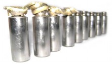
Further investigation showed that this phenomenon was happening due to the excessive wear of the sleeve of the 4/3 directional control valve, combined with the existence of the tank line orifice. When the directional valve spool moved to the problematic side, the internal leakage from the pressure gallery to the tank gallery, aggravated by temperature rise, was enough to raise the pressure inside the tank gallery to 10 bar due to the presence of the small damping orifice.
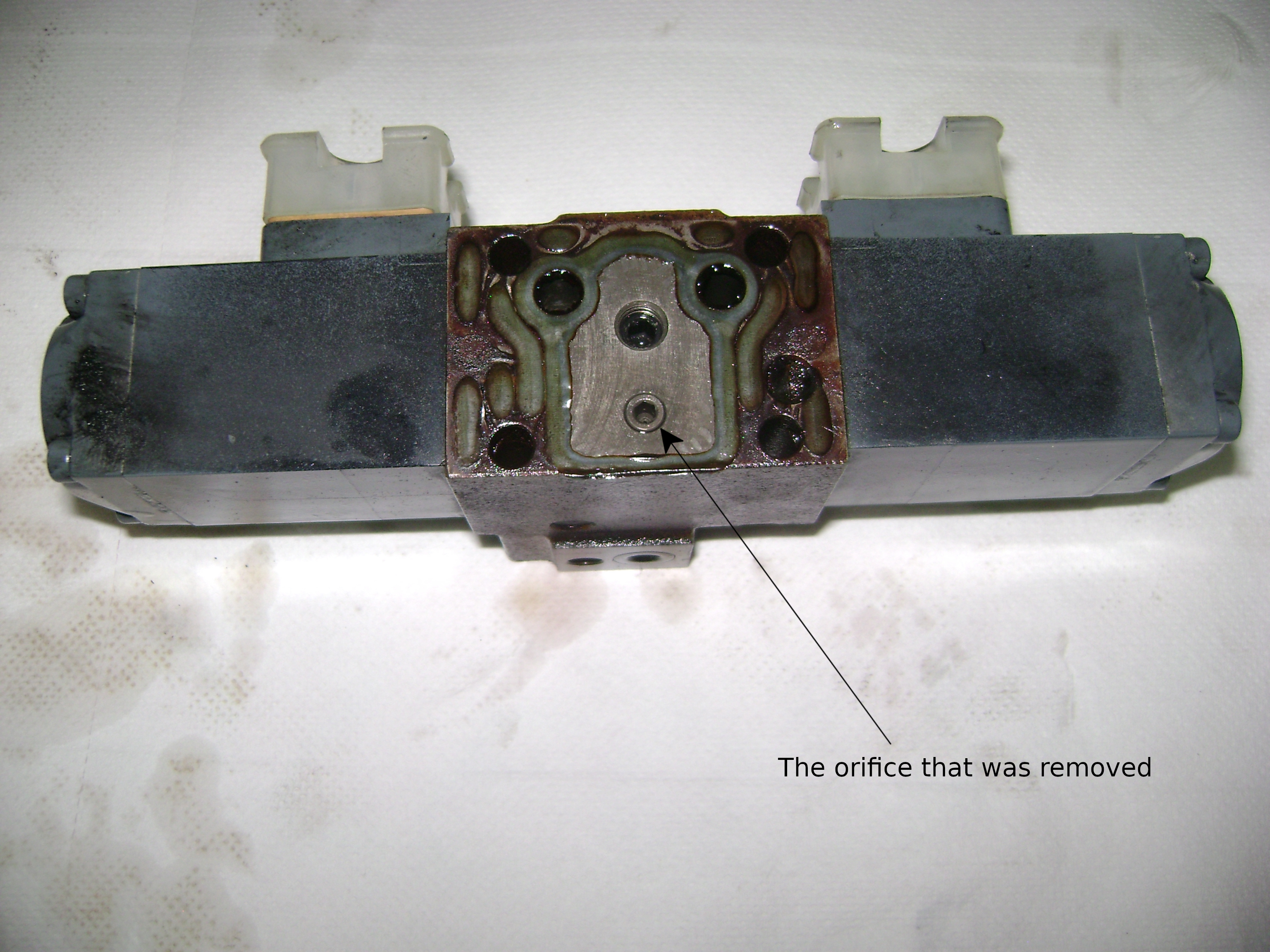

The problem was instantly solved by removing the orifice and the pump was immediately recommissioned, as the machine was needed badly. The client was advised to replace the directional valve ASAP. I don't think they ever did though. I know for a fact that the tug did at least three years of everyday service since that fix... Talk about not fixing what's not broken!
The biggest two lessons I drew from this troubleshooting episode were:
a) to always check both servo pressures at the same time when troubleshooting a closed-loop pump with symmetrical servo-cylinder design and
b) to always carry along enough extra fittings in my test accessories toolbox.