Insane Hydraulics
Bold and audacious blog about fluid power
It all started with a bargain purchase of a used SensoControl Serviceman kit, that turned into a "pickle" (so to speak) when I discovered that nobody at Parker could help when the flow-meter stopped working (aside from quoting a brand new several thousand euro test kit, of course). I am genuinely glad that it happened though, because in the end, it led to a very interesting little project that I will be relating here.
If you use turbine flow sensors (and if you troubleshoot hydraulic equipment, you surely do so) and want to see what's inside, and maybe even one day build a flow (or speed) sensing solution of your own - this series is for you. I'll even reverse-engineer an electronic board used to monitor such flow-meters equipped with an inductive (a.k.a. magnetic or variable reluctance) pickup, which is the most common type of pickup used to detect the speed of moving stuff, like shafts, gears, turbine blades, and whatnot. My case was very specific - I was repairing a broken flow-meter, but the electric circuit and the C code that I will put up (yes - there's code as well!) can be used in other "speed-sensing" projects, so if you are a maker - you may even find a way of apllying them to a completely different scope.
But let me start from the very beginning.
One day an opportunity presented itself - a client was closing his repair business down, and invited us to acquire his Parker flow meter kit at a very budget price. A flow-meter in a hydraulic shop is like a multi-meter in an electronic lab - you can never have too many - so we gladly accepted his offer.


It was an older Parker SensoControl Serviceman, with the SCM-150 display, a 25...600 l/min (7...160 GPM) turbine, and a 600 bar pressure sensor. The kit was very basic, it used outdated cables, the magnetic pickup mounted on the turbine had to be hooked up via an external amplifier, which was pretty bulky and kind of cumbersome to connect, and the display was of the older type, that had two channels, but could only display a single reading at a time - but the combination worked well, and for the price we got it only a fool would complain, so I was happy and used it to diagnose all sorts of "hydraulic shenanigans" up until the day the flow-meter stopped working.
Well, that's life, things break down all the time. And after checking simple things like the cables and power issues, I used another similar kit as a "guinea pig" and quickly pinned down the failure to the external amplifier/signal conditioner:

Recent pickups have this circuitry built-in, but this older model had it inside an external stainless steel tube. I did open it to check for broken wires - but everything I had access to seemed to be OK, and when I removed the end caps, I saw that the OEM opted for potting the complete PCB in silicone.

What do you do in such situations? You reach out to the brand for a replacement, which was exactly what I did, and after a few emails with pictures and detailed explanations of what was needed, I got a reply that, unfortunately, this model of the amplifier was obsolete and no longer available, and, that, in fact, the whole setup was obsolete, and my only viable option was ordering a new complete test kit with accessories.
I get it, I really do. As a person who does sales, I understand that you can't sell what you can't buy. Acquiring a new kit was also not a problem for the company, but letting a perfectly functional flow-sensor go unused, on the other hand, seemed like blasphemy to me, so I decided to use my "reverse-engineering and general tinkering skills" to try and see how this whole "gadgetry" worked and find out if I could come up with a way to diagnose and fix it.
Here's a list of questions that needed answering:
What's inside the flow sensor? I know that there's a turbine inside, of course, but how does it look? How large is it? What bearings does it use? How big is the external radial gap?
The magnetic pickup is sensing the turbine blades passing in front of it - but what is the frequency range? How fast does the turbine spin? Is the relation between the turbine rpm and the flow linear?
The amplifier serves as an "intermediary" between the magnetic pickup coil and the SCM-150 display, but how does it communicate the reading to the display? Is the communication analog or digital? What voltage range or protocol does it use? How does the sensor recognition work? And how does it transform the coil spikes into the data sent to the SCM-150 - is there any digital conditioning or linearization?
All these questions are a normal way to address a troubleshooting situation. All I needed was to know exactly how the system in front of me worked, and as soon as I knew that, I would know what to do to diagnose and fix it or replace it with a custom solution of my own.
The first step was, as always, hunting for documentation. And pretty soon I found this pdf brochure (dated 08/96!), with details of this system. Now I had answers to some my questions.
First - the communication is analog, voltage, 0.1 ... 3,3 V, with 12-bit resolution. At least now I knew what the signal converter was supposed to be putting out. The older manual was even "kind enough" to provide the reference of the 4-pin connectors used in the tool. I love "engineering touches" like this! Parker's newer diagnostic stuff employs 5-pin push-pulls, and they don't give you a reference in the manual for those. I guess selling sensor cables at 200 bucks a pop is a solid business model.
But I digress... Back to our analysis, starting with the turbine. First and most important question - how fast does it spin? To find this out I connected the turbine to our test bench and measured the frequency with my trusted Brymen BM869s.


Here are the values I got (the max flow rate of the bench is, unfortunately, only 90 l/min):

It looks like the frequency to flow relation is more or less linear. If I was to extrapolate the curve, I would be looking at something like 793.33 Hz at 600 l/min (the max flow for this model), and given the fact that the turbine wheel has six blades - this means that at maximum flow rate it spins at about 132 rotations per second or 8000 rpm, which is pretty fast. In any case - now I know the frequency range I need to measure.
Now let us peek inside the damned turbine thing - something I've been wanting to do for a long time!


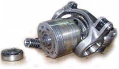
The magnetic pickup has two copper wires kind of flattened on its front face, not sure why. Now the turbine part is interesting. Interesting and simple. The wheel is supported by a simple ball bearing, the shaft is 3/16'' in diameter, and the bearing external diameter is 1/2''. The hole has a diameter of 32mm and the turbine wheel has a diameter of about 30, which means the external gap is about 1 mm. Seems to be a bulletproof system to me.
I actually like this model - it is more compact than the 600-liter series 2 sensors that I've been using. The internal diameter looks the same.


That's it for today. Now I know how fast the turbine wheel of a 600 l/min hydraulic flow-sensor spins, what range of frequencies the signal converter needs to measure, and what type of signal it has to output. Next week I will be "gutting" the signal converter, reverse-engineering its schematic, and then doing the diagnostics. Spoiler alert - the board failed in the worst possible way, which made the troubleshooting and the repair process a whole lot more educative!