Insane Hydraulics
Bold and audacious blog about fluid power
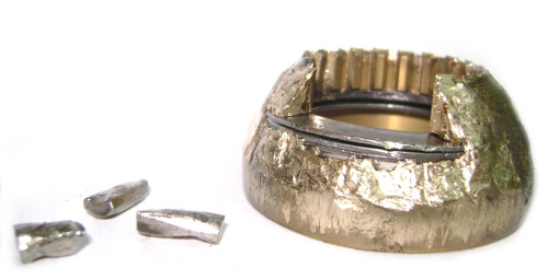
A few days ago we received a "broken" Sauer Danfoss series 51 motor that came from the closed-loop transmission of a street sweeper. The mechanic, who had labeled the motor as "problematic", had years of experience and even had some industrial hydraulics training provided by the brand his company represented. Since it was a warranty claim (the motor had been rebuilt just days before) the case received immediate attention, however, no damage was found when the motor was taken apart. The motor was re-assembled and tested and showed excellent efficiency and controllability. The "troubleshooter" was contacted on the subject, and the consequent dialogue led me to write this article.
The "in-house" motor evaluation technique that had been used for, apparently, a long time, was the good old "check the drain" drill, which is OK for many cases, but not for motors that have built-in flushing and are installed in closed-loop systems. When the mechanic was confronted with the "flushing valve operation theory", he, I must give him credit now, said that if it was normal for such motors to present high case drain flow, then all the machines they had were malfunctioning, and he was sure that this one was very different from all the others (had way more drain flow).
Further interrogation revealed that other machines from their park, equipped with identical transmissions, presented a characteristic spike in the drain flow rate when the machine was just starting to move, and then the case flow would "almost disappear". Naturally, all the flow measurements were performed by disconnecting the drain line, pointing it into a bucket, and visually evaluating the stream. Anything different from this pattern was considered a malfunction. He even said that it was the official brand mechanic "from abroad", who had taught them the technique.
No need to say that I went speechless for some time, fascinated by the conviction and the ardent speech. In the end, the man insisted on re-testing the motor, and it was re-tested, and once again presented no flaws. When I inquired about what the machine was doing wrong, it turned out that the problem was an unstable oscillating movement, rather than a lack of torque. When I asked what the charge pressure reading was when the machine was malfunctioning, he didn't know. Pump servo pressures? No? Motor servo pressures?.. Also no? Ok, suppose you do have (somehow) an excessive leakage from the motor case, but how much exactly, twenty liters per minute, thirty? The answer was prize-winning! - "The oil from the disconnected hose HIT THE WALL, that's how much the case flow was!.." I mean come on, man, seriously, the wall?!!!
I hope you understand that at that moment there was absolutely no way I could defend my point of view. How can one possibly dispute THE WALL argument? Anyhow, he's the one insisting on extra tests and his company is the one paying for it - there's no point in denying the client what he wants, right?
However sad this case may be, this is still a perfect example of how wrong assumptions lead to wrong conclusions. Let's analyze. (Note that I am talking about the classic closed-loop arrangement, with charge pump and charge pressure relief valves incorporated in the main pump, and loop-flushing incorporated in the motor).
First and foremost: a closed-loop component can NOT leak more than the charge pump flow, no matter how damaged it may be. The only place the oil enters the circuit is through the fixed displacement charge pump, which is relatively small, often around 20 percent of the main pump's displacement. So you can have high flow rates inside the loop, but will never be able to get more than the charge pump flow to the outside of the loop because closed-loop circuits do NOT make oil, they just push it around. It is oil companies that make oil.
Theoretically, case-flow of a closed circuit pump or motor can be higher than that of the charge pump, but only for a very short time, and is caused by the "accumulator effect" of hoses during fast pressure changes or oil discharges from the servo-piston system (when you have different servo-piston areas). But we are talking about tenths of seconds here.
In general, when loop flushing "kicks in", the motor will have the drain flow almost equal to the charge pump flow (minus pump's internal leakage) in systems that use a (properly adjusted) relief valve for flushing, or will correspond to a certain setting when a flow regulator (or its variant) is used to limit the flushing flow. Whichever the case may be, drain flow monitoring is a poor technique to evaluate the condition of such a motor, at least not until you eliminate the loop flushing function.
Consider the following - even if you took the motor's cylinder block out (don't take the cylinder block out, though) you would still have the same charge pump flow "leaking out" of the drain port.
But why was that motor's behavior so different from the other machines? To answer this question with full certainty, I would need to see the sweeper for myself, which I didn't. But I have a theory that explains the "initial case flow spike and then small flow" behavior. My imagination draws the following picture:
The motor drain line is disconnected from the system and is pointed into a bucket. The machine is started, and everybody realizes that the system end of the drain line was left open when it pours oil all over the frame. No biggie... The fitting is capped, and the test is resumed. The driver engages the transmission and the machine starts to move. (I imagine the mechanic holding the hose in his hand and staring inside the hose, as he waits for the oil...) As the pressure differential between the motor lines rises during the acceleration, the loop flushing spool shifts, cracking the flushing valve, and the mechanic observes the afore-mentioned "initial" flow spike, thirty percent inside the bucket, seventy percent all over himself and the machine. Although this seems like a lot of fun, the driver understands that it's probably not a good idea to go full throttle when he has a colleague and a bucket hanging from the side of his vehicle, and so he stops accelerating and lets the machine roll at a steady slow speed, at which point there's practically no pressure differential between the loop lines as the machine is moving mainly due to inertia, so the flushing spool returns to the middle position, and the above mentioned "slow" case drain is observed. At this point, the bucket falls to the ground, and the test is stopped. As the bucket is being lifted, the loose hose end is resting on the ground...
Now, jokes aside - let us think for a moment about the main symptom - the unstable movement. It can be caused by one of the two: either unstable flow or unstable motor displacement, which, in turn, can be caused either by an incorrect input or by an internal malfunction. Maybe pump control is faulty. Maybe the motor is receiving a faulty signal to go to smaller displacement, thus increasing the lines delta P, and not allowing the machine to enter the "inertia" mode, loop flushing always working, shooting oil to the motor's casing and over the "ingenious tester"... Anyhow, the pilot pressures and the servo-pressures should have been checked. And yes, this situation is different from other machines they have, but further investigation should have been made to pinpoint the exact origin of the problem.
In fact, in the worst-case scenario, the problem might be motor-related, but might be not detectable on a test stand. For example, excessive wear of the motor's displacement control spool could be causing the self-oscillation of the motor's servo-system. A situation, which is very difficult to simulate on a test rig, as many factors, like pump flow, dynamic torque demands, oil type, etc... are not repeatable and are unique for this particular machine. So it should have been confirmed BEFORE dismounting the motor from the machine.
The main point here is very simple - you can not troubleshoot closed circuits with a bucket. You just can't. You need at least a pressure gauge, a set of test fittings and, most importantly, you must understand how a closed-loop system works to know where to take pressure readings and what conclusions to draw. I do realize that some time ago a friend of a friend of a friend of yours did something like this and it worked, but if you want to succeed regularly, you should rely on "more scientific" troubleshooting approaches and get yourself a proper gear.
I understand that the "bucket flow-meter technique" may be OK for certain extreme 1000-kilometers-away-from-civilization no-other-alternative situations, but it is not suitable for a modern workshop environment. Even so - it wouldn't help much in that particular case.
Such situations also prove that training sessions that don't include feedback and progress assessment, even when provided by an "official brand", are a waste of time and money (all but the coffee breaks, the coffee breaks are great!)
Just another reason to invest in self-education...