Insane Hydraulics
Bold and audacious blog about fluid power
Years of troubleshooting hydraulic machinery have taught me that anything can break or malfunction, no matter how simple and seemingly unbreakable it is. This is exactly why I made it a habit of mine to check everything, whenever I am disassembling a hydraulic component, and I mean EVERYTHING. Sometimes people say about me - "This guy is nuts! Why the hell is he checking this ___ (insert an unbreakable component)?! It's just a waste of time, surely this ___ (insert the component again) can't break!"
Well, my friends, the truth is it can, no matter what, which is why spending an extra minute to check all the components of a hydraulic assembly is never a waste of time. This is especially true when you deal with variable displacement pump controls. Normally, when a client brings you a malfunctioning pump to repair, he will not be able to tell you if the problem is control related. Sometimes, skipping a few simple checks of "apparently unbreakable" parts of a control module can cost you and the machine owner loads of downtime and unnecessary work (and make you look incompetent).
One of the components in pump displacement controls that gets overlooked quite often is the boost pressure shuttle valve (or two check valves, performing the same function). Some mechanics will skip checking it because they either aren't familiar with its function and don't know it is there or think that such a simple thing as a ball/seat check valve is an unbreakable component, hence checking it is a waste of time.
I have witnessed more than once pumps get a complete overhaul and continue to malfunction due to broken boost pressure shuttles that had "dodged" analysis. I mean way more than once, so I am hoping this article will encourage some of my fellow pump repairmen to give those valves a little bit more attention.
First of all their function. The main purpose of these valves is to supply the displacement control with servo pressure from an external pressure source (usually a small gear pump, supplying pilot pressure for the rest of the machine's hydraulic controls) when there is no servo pressure available from the pump pressure port, and, at the same time make sure that the high pressure from it doesn't escape to the low-pressure pilot line. This schematic shows the two most common designs:

More often than not, such a system is used in pumps with proportional displacement controls and stroke limiter controls. With these controls, when the pump is at low or zero displacement and/or there is no resistance to the outlet flow (no load), there is no oil pressure to guarantee the function of the servo system (the cylinder or cylinders that change the swashplate angle) or provide an adequate response time. The existence of this simple system makes sure the servo has a guaranteed oil supply at all times to ensure the correct function of the control.
You can also find this system in large pumps with closed center load sensing controls. Although by definition, a closed center load sensing control is supposed to have at least the delta-P setting pressure at the outlet, sudden system flow demands can create situations when the pressure at the outlet drops abruptly, and, due to the fact that the swashplate and the servo cylinders are massive and the volume of oil in the servo chambers is relatively big, the response time can be too long even with a spring-loaded swashplate. The boost pressure system improves the dynamic response of the control in such situations.
The most common solution is either a couple of ball-type checks or a ball-type shuttle, but other designs (e.g. spool type) are possible. As you can imagine, these valves "smash about" all day long from one seat to the other, which often results in wear of the die-cast body that houses the ball or spool. After many thousands of hours the shuttle literally "eats away" its housing, making a cavity sometimes several times as big as the original. Then several outcomes are possible. Either the ball falls into the new cavity blocking or obstructing the servo pressure supply, or, which is more common for spool-type shuttles, the spool places itself sideways in the widened cavity, and the shuttle becomes a tee, connecting the high pressure to the pilot pressure supply (thus creating a high-pressure leak through the pilot pressure relief valve).
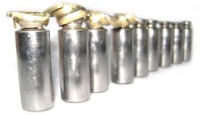
Recently I repaired three AA11VLO250 pumps from a Caterpillar excavator. All three had this problem. You can see the shuttle here:


The pictures don't show this, but take my word for it - you wouldn't believe how deep the small spool "dug into" the cast body, finally placing itself sideways. If such a problem is not detected during disassembly, there is a chance it will not be detected during bench tests. If a technician opts for a test with the boost pressure port plugged (enough to check the rotary group efficiency) the pump will pass the test with distinction. If a technician opts to connect the boost pressure port to a pilot pressure supply, he might confuse the decrease of flow at the outlet, caused by oil escaping through the malfunctioning shuttle and then through the pilot pressure limiter, with the torque limiting function of the displacement control. There will be no excessive case drain flow, so there will be no doubts about the good efficiency of the rotary group. The pump will pass the test, go to the machine, and then face "its majesty unexplained overheating!" Then the consequent troubleshooting will be based on the fact that there is no problem with the recently overhauled pump, and then... Well, let's say the future isn't bright...
Such a problem can be easily solved by machining the cavity and applying a small cartridge-type shuttle valve, of which there are plenty on the market. Other "on the knee" solutions are possible, like applying an external non-return valve, which at least will prevent the high-pressure oil from entering the pilot side till you find a "more technical" solution. Although the pilot oil will still partially escape through the broken shuttle to the pressure side when the outlet pressure drops.
Here you can see the same system in a Liebherr LPVD pump control, that uses two check valves:


As you can see, the high-pressure side check ball has machined a nice round cavity, which it then plugged completely, resulting in control malfunction (no high-pressure limiter function). A possible solution is machining the seat and applying a smaller ball with a guiding sleeve:

Always check the schematic (when available) before evaluating a control's condition, if you see that the control has a servo pressure boost system, make sure to look for and check the shuttle.
Servo pressure boost system operation depends on the correct function of a very simple component - a shuttle valve, which, while simple and robust, is subject to wear. Checking the shuttle valve condition is a quick step that mustn't be skipped, as the consequences of not detecting a malfunctioning boost pressure shuttle can be very, very expensive.