Insane Hydraulics
Bold and audacious blog about fluid power
Just the other day I was asked an opinion about a hydraulic pump shaft seal failure. The client was claiming a warranty, as the pump was only three months old, and the shaft seal was already leaking. It was an all-too-common you-find-em-everywhere bent-axis fixed-displacement unit, mounted on a commercial vehicle. The market is flooded with such pumps, and most of them have one common feature - they don't require a drain connection because the case is internally connected to the suction port.
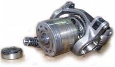
That one was a PZB. Nothing special about its design. Maybe the front bearing. If you look at the cutaway drawing below, you'll see that the outer shaft bearing is isolated from the case oil. A lot of pump manufacturers do this, the front bearing is sealed and has grease inside.

A glance at the pump in question ruled out any warranty, as the bearing's outer shield had been pushed out by oil pressure, which meant that the pressure inside the pump rose at least higher than maximum pressure the shaft seal could take, which for these seals was around 3 bar.
Further analysis of the pump revealed severe scoring of the valve plate, cylinder bores and piston rings. So, there were two problems present. First - somehow a rather high positive pressure was created inside the pump's casing (connected internally to the suction line!), and second - the hydraulic oil was very dirty.
When the client heard about contaminated oil, he reassured that the oil was clean. "There's no way my system can be contaminated!" - he said - "The whole hydraulic installation is brand new!" This is one situation I see too often. There are plenty of people who still believe that new hydraulic installations are clean. In industrial hydraulics "new" equals "contaminated", especially when talking about new pipes, tanks and hoses. Even the new oil that comes from a sealed drum has cleanliness level that's not clean enough for most hydraulic components. I confess I learned not to sweat it - such myths are responsible for a good half of our business, you know.
Now the part with the blown seal is much more interesting. Let us think for a moment about how it is possible to create a positive pressure inside a pump that has its casing connected internally to the suction line. Seems impossible, doesn't it? A suction line is a low pressure region by definition, but even if we could somehow find a way to direct oil to it - wouldn't it just drain to tank through a presumably large connection?
The correct answer to these questions is "Yes, of course, but only in a properly built and maintained system".
The thing is - if a hydraulic system is well designed and put together, there' no way for such a failure to happen, but nothing is ideal in this world, and more often than not systems are built on the "what you have in the shop and/or can afford" basis, rather than "let us, for just this once, build a proper hydraulic system" basis. I don't want to go into that, I am also a human being. What I want - is to talk about ways of developing a case pressure in a drain-to-suction connected fixed displacement pump big enough to bust a shaft seal.
First - normal operation. It may seem that during normal operation - i.e. - the pump sucking through its suction port, the excessive internal leakage of the pump can't raise the case pressure, but it really depends on the size of the drain-to-suction channel. Some manufacturers leave a huge opening, which is probably capable of absorbing the pump's nominal flow with a minimal pressure drop, and some leave but a narrow gap, and in the latter case, if the pump is indeed worn out, especially in the piston/bore area - the case pressure can become "extremely positive", pushing the said shaft seal lip inside out.
But, hey - the excessive internal leakage is a common shaft seal buster, where's fun in that? Let us consider other, more "exotic" possibilities.
The second best place to cause a pressure strain on the tank side of any hydraulic system would be, of course, the tank breather. Sometimes the return flow of a piston-type actuator can be significantly larger than the pump flow, and in that case, if the tank is not properly vented all sots of funny things can start happening, one of which being a shaft seal popping out.
And finally, we get to the most spectacular way of all - the backflow. First - the suction line must be "a little bit on the narrow side" for this method to work, and second - you must find a way for the oil to flow back into the suction line.
Let us consider the "slightly narrow suction line" first. A common situation - you get an 80-100 l/min pump, look at the flow nomogram, consider the maximum recommended suction flow speed, and say something like - "No way I am putting an inch and a half hose here". But you do have a one-inch hose in the shed, so you grab it and devise a neat-looking 3-meter long suction line from whatever fittings you had around. And yes, there's a couple of elbows in it as well. It will work, of course. And even if you look at the standard hose pressure drop chart - 10 feet of one-inch hose drop only about 2 psi at this flow - so... we're all good, right? Nope! The chart is for hose lengths only. The fitting shanks, the elbows, the possible strainer in the tank will all add up - I promise you that.
Now - for the backflow. The best way to achieve it would be, of course, by replacing a left-hand pump with symmetric ports with a right-hand model - but this is too obvious and the failure is instant. What we want here is the "true" backflow - i.e. the flow coming back from the system through the pressure line and turning the pump like a motor (with the PTO disengaged, obviously). And I've seen this happen many times - in systems that are used to lift and hold loads in the air (cranes, tipper trucks, and whatnot). A suspended load is a great way of providing backflow if there's no check valve at the pump outlet or in the respective directional control valve. If the PTO is disengaged and the load is still in the air - move the DVC spool and hear the pump go "z-z-z-z". That's backflow for you - through the rotating pump and the suction line back to the tank. Make the load big enough and couple it to the "economical" suction line, colder oil, worn-out pump, and a narrow drain-to-suction channel in the pump - and you just gained yourself a busted seal, congratulations!
I like considering "hypothetical" hydraulic scenarios. It is fun!
In any case, when a shaft-seal failure happens, the complete hydraulic circuit must be checked for possible causes.