

SUBJECT: Mechanical Seal hydraulic balance 8-01
Seal hydraulic balance is one of the most effective tools we have to counter the detrimental affects of heat being generated in the pump stuffing box. The original patent for hydraulic balance was granted in 1938, but the concept has never been adopted by the "original equipment manufacturer" (O.E.M.), and so to this day it remains only an "after market" product.
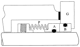
Hydraulic balance is very easy to understand; please look at the following diagram:

A = The spring loaded face with an area of 2 in2 (6 cm2)
B = The stationary face held to the front of the stuffing box by gland "G"
P = The hydraulic pressure in the stuffing box is given as 100 psi (10 Kg./cm2)
To understand hydraulic balance you must know that:
* Multiply this number by gravity (9.8 m/sec2) and you get Newtons of force.
There are at least two forces closing the seal faces:
There are at least three forces trying to open the seal faces:
Let's look at these forces individually and in a little more detail!
First we'll look at the closing forces:
Now we'll look at the opening forces
1. First the hydraulic force:
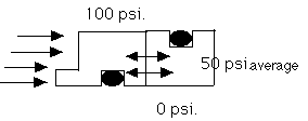
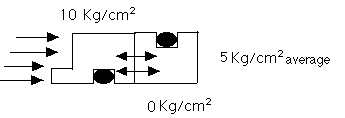
Look at the following diagram: If we assume a straight line or linear pressure drop across the seal faces, we would get an average of:

or 5 Kg/cm2 x 6 cm2 = 30 Kilograms of force trying to open the seal faces.

2. Centrifugal force is acting on the spring loaded face (A) trying to spin it perpendicular to the rotating shaft.
3. Seal faces are lapped to within three helium light bands or slightly less than one micron. This slight waviness is enough to generate hydrodynamic lifting forces as we try to compress non-compressible liquid t trapped between the lapped faces.
Two forces closing, and three forces opening the seal faces. If the closing forces are the greater forces, the seal will generate heat that is often destructive, but always a waste of energy and pump efficiency. If the opening forces are the greater forces the seal will leak and that's never desirable.
A balanced seal, by definition, balances these opening and closing forces so that the seal will not get hot and it will not leak. How is that accomplished? Since the hydraulic closing forces were twice the opening forces (100 psi. vs. 50 psi.) we have installed a sleeve inside the seal to reduce the closing area and reduce the closing force. Look at the following diagram for an explanation:

You can now see that the 100 lbs/in2 (10 Kg/cm2) is now pushing on only 1in2 (3 cm2) because the inner sleeve is attached to the shaft and cannot move. The opening force remains the same. The numbers look like this:
As you can see, we have eliminated the hydraulic forces from acting to open or close the seal faces. This leaves only the spring force to close the seal and the hydrodynamic and centrifugal forces to try to open the seal faces. The question then becomes, "can the spring force balance the other two?"
And there is another point to consider; was the pressure drop across the seal faces really linear?
All of these questions were answered way back in 1938 by physical testing. The final design solved the problem by overbalancing the closing hydraulic forces to compensate for:
Look at the following diagram for the final result:

Seventy percent (70%) of the seal face area is exposed to the hydraulic closing force instead of the fifty percent (50%) shown in the previous drawing. This is the standard 70-30 balance used by most mechanical seal companies. The seal designer can increase or decrease the percentage of over balance by changing the stepped sleeve diameter. We would want to do this to:
All that was required to hydraulically balance the seal was the simple low cost sleeve, but it is this additional cost that is keeping the original equipment manufacturer from adopting the design as his standard. The "bottom line" is that with an un-balanced seal design you either suffer the consequences of adding heat to the stuffing box area, or having to provide cooling to remove the heat that is being generated by the un-balanced seal.
Keep in mind that this heat is never desirable because:
Allways specify hydraulically balanced seals. The unbalanced versions do not make any sense. In addition to low heat generation, balanced seal have other advantages:
For information about my CD with over 600 Seal & Pump Subjects explained, click here