Insane Hydraulics
Bold and audacious blog about fluid power
Note: If you want to jump directly to the hydraulic digram that draws itself press here.
Terms like post-compensation, flow-sharing, and hey, since we're at it, let us throw in the pre-compensation as well - come in very handy when you want to talk about predictable flow control in hydraulic systems, especially when you know what these terms mean... I don't know about you, but even when I was only starting to learn oil-hydraulics, I had zero trouble understanding the pre-compensated circuits, and all the trouble in the world figuring out the post-compensated ones. For some reason, this whole flow-sharing "business" used to make my brain want to explode whenever I tried to wrap my head around it. And from what I keep hearing from other techs - I am not alone...
So this is exactly what I want to start addressing in this article - the very interesting topic of post-compensation, often referred to as "flow-sharing". And for those of you who started to "nervously fiddle" in their chairs - "but post-compensation and flow sharing is not the same thing, mate!..:" - let me say it right away - I see where you're coming from and I will address the use of these terms later, ok?
There are numerous online publications devoted to post-compensation and flow sharing, however in my opinion, while being indeed of a very high quality, most of these articles are written by very experienced engineers for very experienced engineers. They do explain the function and benefits of post compensation, but they fail to give a "for dummies" explanation of the basic principle behind all this flow-sharing mumbo-jumbo. And what I want to achieve here is exactly that - i.e. an "uncomplicated" explanation of the main principle standing behind the flow-sharing compensator configuration.
In order to be able to understand how pressure compensators work, the only thing you must understand is the following: when oil flows through a metering orifice, the pressure drop across the orifice is proportional to the flow rate, and inversely proportional to the orifice size. Actually, the relation is close to quadratic, but it doesn't matter here, really - as long as you understand that keeping a constant pressure drop across an orifice means keeping the flow rate stable, you will be able to understand all there is to pressure compensation both in its "pre" and "post" flavors. And, of course, you must comprehend that the main purpose of any pressure compensated flow control system is to keep the flow to an actuator stable by automatically compensating for the changes in load induced pressure, or, in other words - to secure accurate and predictable function control.
Now, with that out of the way, let us start with simplifying things to the extreme, and let us forget about all the "paraphernalia extra" like variable flow pumps, unloading valves, load sensing, efficiency, overheating, etc., and not even consider flow saturation at this point. Let us create a very basic pressure source circuit, composed of a fixed displacement pump working against a relief valve set at, say, 200 bar. Then let us introduce our variable load, represented in the diagram by another relief valve, and let us imagine that our load demand can vary form 0 to 100 bar, and finally let us slap in a variable metering orifice (think - needle valve) and see what happens:
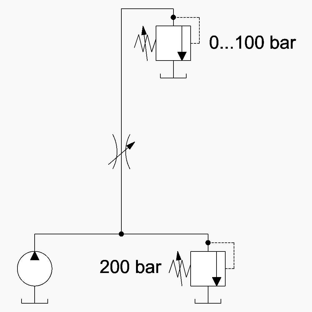
This system is, obviously, miles from being perfect. Whenever the load pressure changes, so does the pressure drop across our metering element, and, consequently, the flow to our actuator - definitely not a perfect scenario.
Well, about 70 years ago someone very smart looked at a similar system and said - "Oi, lads! We've got ourselves an orifice and a pressure drop across it, and the flow is gamboling up and down like a bedlamite, it does! What if we, lads, fashioned a way to keep this pressure drop stable? - We'd be getting ourselves the most steadfast unwavering flow on the face of the earth, would we not?!" And so, the "lads" connected two pilot lines before and after the restriction (to "tap" into the aforementioned delta P), and applied them to both sides of a two-way valve, spring biased in the open position and mounted upstream the orifice. In such way, whenever the pressure differential acting on the spool produced more force than the bias spring, the spool would move towards closed position, throttling the flow and thus effectively limiting the delta P (and, consecutively, the flow) across the orifice in a self-regulating fasion. And just like that the pre-compensated flow control was born:
Now our circuit is much better - we set the function speed with the needle vale, and watch happily how our flow remains stable and independent from the load induced pressure.
It is very important to understand the main key feature of this system - the compensator is normally open, and it works (or compensates, if you will), only after a certain pressure drop (whose threshold is defined by the compensator spring) is reached across the metering orifice. This means that such system can be regarded as a "flow limiter".
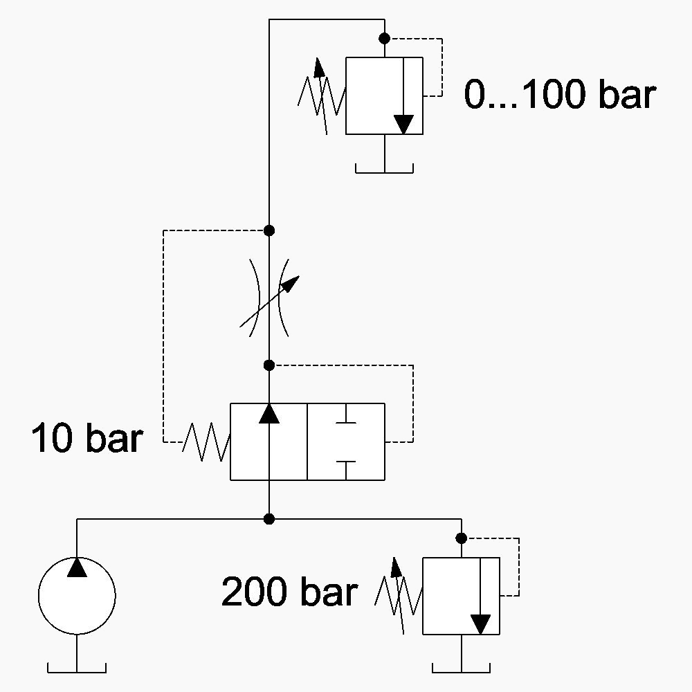
In our "oil boiler" the compensator valve was placed upstream the orifice, but you could actually move it downstream and it would work just the same. In my opinion, moving the compensator downstream does, actually, qualify it as a post-compensated system (albeit not suitable for flow-sharing, but this is the matter for part II), but it doesn't change the fact that it still obeys the same principle - it is still a biased-open flow limiter, in which the compensating pressure drop across the metering element is defined by the spring:
Such post-compensated normally open flow control arrangement is often found in fixed orifice cartridge-style flow control valves, because constructively this is the simplest (and cheapest) design solution that you can get - consisting of a single spring biased spool with an orifice in it, like this one here:

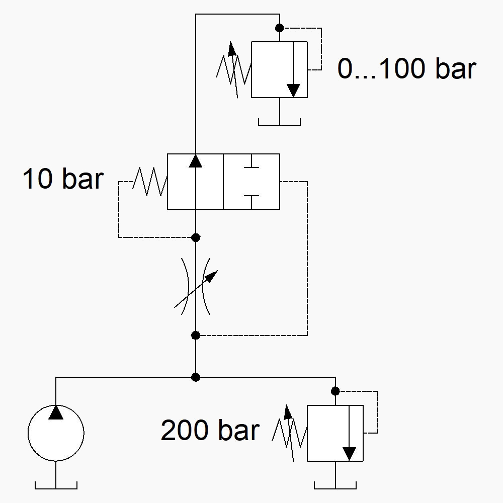
I hope you're still with me, because we have arrived to the point when the main post-compensation principle is about to be revealed. Some years later, another smart person looked at the self same system - and said - "Oi! We've got ourselves an orifice here, and we need this constant 10 bar pressure drop to be able to control things right, don't we, lads? But hold on for a minute - we've got the 200 bar in the orifice inlet, so in order to get our 10 bar delta P we should have 190 bar on the outlet... So then why don't we do just that, lads? Why don't we fashion a way to induce the 190 bar on the outlet of our orifice? We'd be getting ourselves the drop that we wanted!" And so the "lads" took a sequence valve, placed it downstream the orifice, and adjusted it to 190 bar, like so:
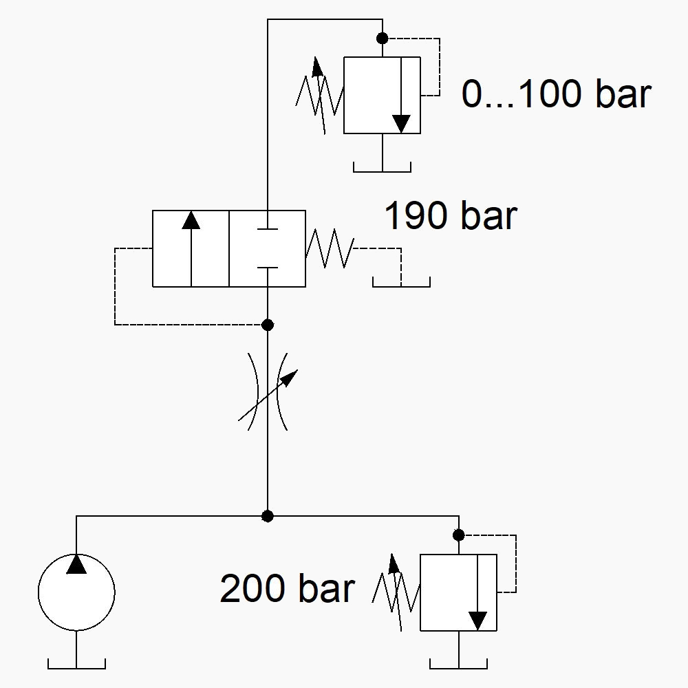
And there you have it - a different circuit that delivers a similar result. This arrangement provides the same constant 10 bar pressure drop across the metering element, thus also securing load independent flow control. Note that this is a sequence valve, and not a relief valve - although the valve and the load are connected in series, the load induced presure does not add to its setting (see the spring chamber vented to tank?). In fact - the strong 190 bar spring could be replaced with a 190 bar pilot pressure (coming from some "magical" pressure source) acting on the spool:
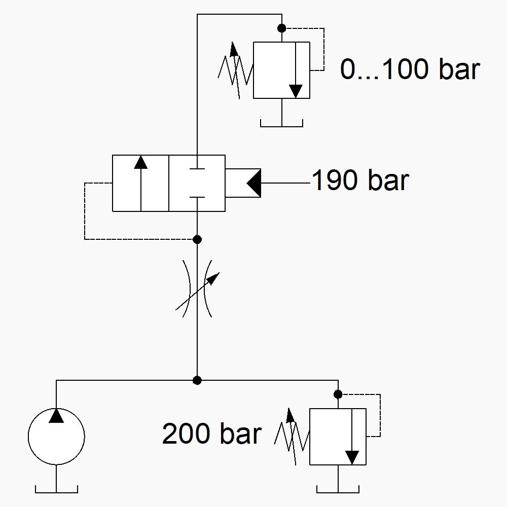
And that's all there is to it - while the pre-compensated system is based on a normally open compensator that works as a "flow limiter", that reads the delta P across the orifice and keeps it below the spring defined setting - the post-compensated system works as a "pressure inducer", making sure the pressure downstream the metering element doesn't go lower than a certain setting, defined by a supplied pilot pressure (or, as it is in our over-simplified example, by a very strong spring).
Grasping this principle (the difference between a "flow-limiter" and a "pressure-inducer") was an eye-opener for me, and as soon as I started to call these circuits by those names, their function became clear to me. I will discuss how these compensators behave in systems with multiple actuators under normal and flow saturation conditions in the part II of this article.
Now - for the eye candy. Everybody loves hydraulic diagrams that draw themselves! What? You've never heard about one?
Then here's one for you, explaining in a couple of clicks the post-compensation principle that was discussed in this article.